Transcription of Pocket Guide to Tightening Technique - Atlas Copco
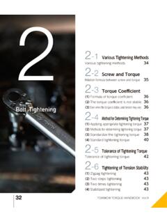
1 Pocket Guide TO Tightening TECHNIQUE2 Pocket Guide TO Tightening TECHNIQUE3 Pocket Guide TO Tightening TECHNIQUEPOCKET Guide TO Tightening TECHNIQUEC hapter ..Page 1. Why threaded fasteners? ..4 2. The screw joint ..4 3. Clamping force ..6 4. Effect of lubrication ..7 5. Screw quality classification ..8 6. Joint types ..10 7. torque and angle ..11 8. Measurement methods ..12 9. The Tightening process ..14 10. Mean shift ..15 11. Standards for measurement ..16 12. Certification ..16 13. Errors in Tightening ..17 14. Damaged threads ..17 15. Missing joint components ..17 16. Relaxation ..17 17. Prevailing torque ..18 18. Tightening Summary ..254 Pocket Guide TO Tightening TECHNIQUEPOCKET Guide TO Tightening TECHNIQUEThis booklet provides an introduction to the Technique of us-ing threaded fasteners for assembling components, the ap-plication of power tools for the assembly and the influence of tool selection on the quality of the WHY THREADED FASTENERS?
2 There are several ways of securing parts and components toeach other, gluing, riveting, welding and , by far the most common method of joining compo-nents is to use a screw to clamp the joint members with anut or directly to a threaded hole in one of the advantages of this method are the simplicity of designand assembly, easy disassembly, productivity and in the end THE SCREW JOINTA screw is exposed to tensile load, to torsion and sometimesalso to a shear stress in the screw when the screw has been tightened tothe design extent is known as the tensile load corresponds to the force that clamps the joint members together. External loads which are less than the clamping force will not change the tensile load in the screw. On the other hand, if the joint is exposed to higher external loads than the pre-stress in the bolt the joint will come apart and the tensile load in the screw will naturally increase until the screw Guide TO Tightening TECHNIQUET orsion in the screw results from friction between the threadsin the screw and the screws are also exposed to shear loads which occur when the external force slides the members of the joint in relation to each other perpendicular to the clamping force.
3 In a properly designed joint the external shear force should be resisted by the friction between the components. A joint of this kind is called a friction joint. If the clamping force is not sufficient to create the friction needed, the screw will also be exposed to the shear load. Joints are frequently designed for a combination of tensile and shear screw is made up of the shank and the head. The shank is threaded, either for part of its length or for the full length from the end to the head. Longer screws are usually only partly threaded. There is no need to make a thread longer than is necessary to tighten the joint as this will only make the screw more expensive and reduce the tensile dimensions of threads, the shape of the thread and the pitch, the distance between successive threads, have been standardized.
4 In practice there are only two different stand-ards used today in industry; the Unified standard UN, origi-nally used in the Anglo-Saxon countries, and the European Metric standard load and tensile screw forceTensile loadTensile loadShear loadShear load6 Pocket Guide TO Tightening TECHNIQUEA part from the basic dimensional differences the UN and M standards have different angles and depths of thread. Both standards include separate specifications for fine threads. The UN fine thread standard UNF is quite common parallel to the normal UNC CLAMPING FORCEIn general it is desirable that the screw is the weakest member of the joint. An over-dimensioned screw makes the product both heavier and unnecessarily expensive. As a standard screw is usually comparatively inexpensive it is preferable that the screw should be the first part to , in most cases the dimensions of the screw are not critical for the quality of the joint.
5 What is decisive is the clamping force, whether it is sufficient to carry all the load for which the joint is designed, and whether the joint will re-main tight enough to prevent loosening if exposed to pulse problem is that there is no practical way to measure the clamping force in normal production situations. Consequently the value of the clamping force is usually referred to as the Tightening the clamping force is a linear function of both the turning angle of the screw and the pitch of the thread, there is a direct relation between the clamping force and the Tightening torque within the elastic range of the screw elongation. However, only about 10% of the torque applied is transferred into clamping force. The remaining Tightening force is consumed in friction in the screw joint 40% of the torque to overcome the friction in the thread and 50% in friction under the screw =mm/rotation7 Pocket Guide TO Tightening TECHNIQUE4.
6 EFFECT OF LUBRICATIONIf a screw is lubricated, the friction in the threads and under the head is decreased and the relation between Tightening torque and clamping force is changed. If the same torque is applied as before lubrication, a lot more torque will be trans-formed into clamping force. At worst this might lead to the tension in the screw exceeding the tensile strength and break-ing of the the other hand, if the screw is completely dry of lubricant the clamping force might be too small to withstand the forces for which the joint is designed, with the risk that the screw becomes 1. Friction in threads of different materialNut materialDryLightly Zinc coatedPhosphorous Zinc platedElectro Zinc Guide TO Tightening TECHNIQUE5. SCREW QUALITY CLASSIFICATIONWhen a screw is tightened and the clamping force starts to build up, the material of the screw is stressed.
7 After a short time when the thread settles the material will stretch in pro-portion to the force. In principle, this elongation will continue until the stress in the screw is equal to the tensile strength at which the screw will break. However, as long as the elon-gation is proportional to the stress the screw will regain its original length when the load is removed. This is known as the elastic a certain stress, known as the yield point, plastic defor-mation of the material in the screw will occur. However, the screw will not break immediately. torque will continue to increase but at a lower torque rate during the deformation above the yield point. The plastic deformation will result in a permanent elongation of the screw if the joint is very accurate clamping force requirements this area is sometimes deliberately specified for the Tightening the plastic area breakage pointStressAngular displacementFailure9 Pocket Guide TO Tightening TECHNIQUEM-Threaded screwboltsTightening torque Nm, according to ISO 898/1 The material qualities of screws are standardized, the amount of tensile stress they can be exposed to before the yield point is reached and before breakage occurs.
8 All screws should be marked according to their Bolt Grade a classifica-tion standard in a two-digit system where the first digit refers to the minimum tensile strength in 100 N/mm2 and the second digit indicates the relation between the yield point and the minimum tensile strength. For example: Bolt Grade desig-nates a screw with 800 N/mm2 minimum tensile strength and a yield point of x 800 = 640 7. 7. 2 0M2736043560096113501620M304925908191310 18402210M3685510301420228032103850M42136 0227036105 1106140M4516902820451063407610M482040340 0545076609190 Table 2. Table for different classes of Guide TO Tightening TECHNIQUE6. JOINT TYPESS crew joints vary not only in size but also in type, which changes the characteristics of the joints. From a tighten-ing point of view the most important quality of a joint is the hardness.
9 In figures this can be defined as the torque rate , which is the Tightening angle necessary to achieve the recom-mended torque of the screw dimension and quality in ques-tion measured from the snug level the point at which the components and the screw head become torque rate can vary considerably for the same diameter of screw. A short screw clamping plain metal components reaches the rated torque in only a fraction of a turn of the screw. This type of joint is defined as a hard joint . A joint with a long screw that has to compress soft components such as gaskets or spring washers requires a much wider angle, possibly even several turns of the screw or nut to reach the rated torque . This type of joint is described as a soft joint. Obviously the two different types of joints behave differently when it comes to the Tightening of screw Guide TO Tightening TECHNIQUE7.
10 torque AND ANGLEAs mentioned above, the Tightening torque is for practical reasons the criteria normally used to specify the pre-stress in the screw. The torque , or the moment of force, can be measured either dynamically, when the screw is tightened, or statically, by checking the torque with a torque wrench after specifications vary considerably depending on the quality demands of the joint. A safety critical joint in a mo-tor car, such as the wheel suspension, cannot be allowed to fail and is consequently subject to very stringent tolerance requirements. On the other hand a nut for securing the length of a workbench height adjustment screw is not regarded as critical from a clamping force point of view and no torque re-quirement may be higher level of quality control is reached by adding the Tightening angle to the measured parameters.