Transcription of Pop-Up - Legrand
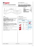
1 87045 LIMOGES Cedex Phone : 05 55 06 87 87 Fax : 05 55 06 88 88. Pop-Up Number(s) : 0 540 00 to 03, 0 540 05 to 08, 0 540 10 to 13, 0 540 15 to 18, 0 540 20 to 23, 0 540 26, 0 540 28, 0 540 31, 0 540 33, 0 540 40 to 43. CONTENTS PAGES. 1 to 3. 4 to 8. characteristics 9 to 11. to Use 12. 1 RANGE. - a solution for integrating wiring accessories in office furniture or in floor (5 finishes). - products conform to NFC 61-314 / EN 60 670-1 / EN 60 670-23. Desk/table Use the Kit for desk/table/raised floor - Power - Data Cat6. - AV. Raised floor Concrete Use the backbox for concrete floor - Power Data sheet : F01367EN/00 Updated : 01/10/12 Created : 01/10/12. 1 / 12. Pop-Up Number(s) : 0 540 00 to 03, 0 540 05 to 08, 0 540 10 to 13, 0 540 15 to 18, 0 540 20 to 23, 0 540 26, 0 540 28, 0 540 31, 0 540 33, 0 540 40 to 43.
2 1 RANGE (continued) 1 RANGE (continued). Two types of Pop-Up ; - 5 finishes available : Simple Pop-Up : 3 modules : Brushed Brass Matt Aluminium 4 modules : Brushed Stainless steel Double Pop-Up : Matt Black 6 modules : Glossy White 8 modules : Compatibility power/dat : Power Data Concrete yes No Raised floor yes Compatible Cat 6. Furniture/desk yes Compatible Cat 6. - pack by 1. Note : screw delivered with Pop-Up . 16A 250 VA, 3680W at 230V per circuit Data sheet : F01367EN/00 Updated : 01/10/12 Created : 01/10/12. 2 / 12. Pop-Up Number(s) : 0 540 00 to 03, 0 540 05 to 08, 0 540 10 to 13, 0 540 15 to 18, 0 540 20 to 23, 0 540 26, 0 540 28, 0 540 31, 0 540 33, 0 540 40 to 43. 1 RANGE (continued). Pop-Up selection chart to be equipped: - with Mosaic or Arteor wiring devices - with 1 installation kit for raised floor/desk or with 1 backbox for concrete floor Finishes 3 modules 4 modules 6 (2x3) modules 8 (2x4) modules Brushed 0 540 15 0 540 16 0 540 17 0 540 18.
3 Brass Matt 0 540 10 0 540 11 0 540 12 0 540 13. Aluminium Brushed 0 540 20 0 540 21 0 540 22 0 540 23. Stainless steel Matt Black 0 540 26 0 540 28. Glossy 0 540 31 0 540 33. White Equipped Pop-Up selection chart (installation kit included). Finishes References Pop-Up Glossy White 0 540 44. 4modules equipped with : 1 socket German standard 2P+E with 2m cord +. 2 RJ 45 sockets Cat6 UTP with 3m cord Brushed Stainless steel 0 540 45. 4modules equipped with : 1 socket German standard 2P+E with 2m cord +. 2 RJ 45 sockets Cat6 UTP with 3m cord Glossy White 0 540 46. 8 (2x4) modules equipped with : 2 sockets German standard 2P+E with 2m cord +. 2 RJ 45 sockets Cat6 UTP with 3m cord + HD 15 jack Brushed Stainless steel 0 540 47. 8 (2x4) modules equipped with : 2 sockets German standard 2P+E with 2m cord +.
4 2 RJ 45 sockets Cat6 UTP with 3m cord + HD 15 jack Data sheet : F01367EN/00 Updated : 01/10/12 Created : 01/10/12. 3 / 12. Pop-Up Number(s) : 0 540 00 to 03, 0 540 05 to 08, 0 540 10 to 13, 0 540 15 to 18, 0 540 20 to 23, 0 540 26, 0 540 28, 0 540 31, 0 540 33, 0 540 40 to 43. 2 INSTALLATION 2 INSTALLATION (continued). On concrete floor: On concrete floor (continued). Pop-Up is delivered with terminal block. Under concrete floor: - minimum depth = 60mm Terminal block Use the backbox for concrete with conduits diameter 20mm It is necessary to close the backbox for concrete using the protection cover delivered with before pouring the concrete in order to prevent that the concrete to enter in the backbox The backbox for concrete is delivered with protection cover: Protection cover Example of simple Pop-Up on concrete floor : Pop-Up Pop-Up Pop-Up Pop-Up 3mod 4mod 6 (2x3) mod 8 (2x4) mod r f r f r f r f 0 540 00 0 540 01 0 540 02 0 540 03.
5 Note: the old flush-mounting boxes ref 6503 90/91/92 for floor boxes sockets are compatible with new Pop-Up X Catalogue Export 2009/20011 on page 778;. Example of double Pop-Up on concrete floor : X. Dimensions (fixing centres) : X(mm). 3 mod 84. 4 mod 6 (2x3) mod 194. 8 (2x4) mod 239. Data sheet : F01367EN/00 Updated : 01/10/12 Created : 01/10/12. 4 / 12. Pop-Up Number(s) : 0 540 00 to 03, 0 540 05 to 08, 0 540 10 to 13, 0 540 15 to 18, 0 540 20 to 23, 0 540 26, 0 540 28, 0 540 31, 0 540 33, 0 540 40 to 43. 2 INSTALLATION (continued) 2 INSTALLATION (continued). On the desk or on the raised floor On the desk or on the raised floor (continued). Cut the desk or raised floor : System overview. Power X. Installation kit Data Y. HD15. X(mm) Y(mm). To fix on the raised floor/desk 3 mod 108 (+/-1mm) 108 (+/-1mm).
6 4 mod 108 (+/-1mm) 131 (+/-1mm). References Installation kit for Pop-Up 6 mod 108 (+/-1mm) 218 (+/-1mm). 0 540 05 Installation kit 3modules 8 mod 108 (+/-1mm) 263 (+/-1mm). 0 540 06 Installation kit 4modules Minimum depth of desk plate 15mm (40mm max). 0 540 07 Installation kit 6(2x3) modules Positioning of the fixation supports in the desk 0 540 08 Installation kit 8 (2x4) modules Composition : 2. 1 insulation unit 1. 1 Clamp support 3 4. 2 parts fixations supports Holes to fix on the 4 corners with screws if needed 5. Fixations supports, allows to install the product directly on the raised floor/desk. 6. Data sheet : F01367EN/00 Updated : 01/10/12 Created : 01/10/12. 5 / 12. Pop-Up Number(s) : 0 540 00 to 03, 0 540 05 to 08, 0 540 10 to 13, 0 540 15 to 18, 0 540 20 to 23, 0 540 26, 0 540 28, 0 540 31, 0 540 33, 0 540 40 to 43.
7 2 INSTALLATION (continued) 2 INSTALLATION (continued). On the desk or on the raised floor (continued) Installation for power sockets : Before the installation of the kit, remove the terminal block delivered Assembly of the power cable in the Pop-Up before the connection to with the Pop-Up (not to be used in this configuration) wiring devices : 1- Remove the cable clamp Please use the clamp support if you need power. Wiring scheme with stripping : 2- Insert the cable through the clamp support. A : put the clamp support on the cylindrical dumper fix with the earthing screw B : earth on the metal part on the Pop-Up Support clamp is not necessary if you use only data socket Installation of the insulation unit. 3- Let exceed only the stripped part of the cable inside the Pop-Up 4- Lock the cable with the cable clamp Position your fingers as represented above, press the kit and insert it in the Pop-Up until clic.
8 Connect the sockets cable before clipping on the support. Data sheet : F01367EN/00 Updated : 01/10/12 Created : 01/10/12. 6 / 12. Pop-Up Number(s) : 0 540 00 to 03, 0 540 05 to 08, 0 540 10 to 13, 0 540 15 to 18, 0 540 20 to 23, 0 540 26, 0 540 28, 0 540 31, 0 540 33, 0 540 40 to 43. 2 INSTALLATION (continued) 2 INSTALLATION (continued). Installation for data sockets : Installation for Audio/video sockets : Assembly of the Ethernet cable for network in the Pop-Up before the Assembly of the Audio cable in the Pop-Up before the connection to connection to RJ 45 sockets : HD 15 sockets : Remove the cable exit : Remove the cable exit : 1- Cut out the protective cap according to the number of cable (4 1- Pass the cable through the support to connect the HD 15 sockets max) 2- Break the strip allowing the passage of the cable 3- Position the cable in its receptacle and reposition the cable exit.
9 2- Pass the cables through the support to connect the sockets and clip them on the frame 4- Lock the cable using the cable tie. 3- Reposition the cable exit and block the cable using the cable tie. Reassemble the cover with its screw to finalize the installation Reassemble the cover with its screw to finalize the installation Note: in the case of audio/video mixed equipment (HD 15 + jack ) equipped with two cords, proceed in the same way. Data sheet : F01367EN/00 Updated : 01/10/12 Created : 01/10/12. 7 / 12. Pop-Up Number(s) : 0 540 00 to 03, 0 540 05 to 08, 0 540 10 to 13, 0 540 15 to 18, 0 540 20 to 23, 0 540 26, 0 540 28, 0 540 31, 0 540 33, 0 540 40 to 43. 2 INSTALLATION (continued) 2 INSTALLATION (continued). Installation of Pop-Up on the desk or on the raised floor by screwing Positioning of data cables on the raised floor: on the fixation supports To respect the bend radius for data cables, it is necessary to fix the cables by respecting a radius higher than 80mm (curve of the cable at the exit on the kit and the points of fixing of the cable on the fixation supports).
10 R=80mm or ( 160mm). The oblong holes allow the passage of the cable ties to generate the loop of RJ 45 cable and to respect the bend radius for data cables. Maximun cable for data in assembly in a raised floor : cable 6a F/UTP. Note : if installation with several cables, they must be attached together using a cable tie Data sheet : F01367EN/00 Updated : 01/10/12 Created : 01/10/12. 8 / 12. Pop-Up Number(s) : 0 540 00 to 03, 0 540 05 to 08, 0 540 10 to 13, 0 540 15 to 18, 0 540 20 to 23, 0 540 26, 0 540 28, 0 540 31, 0 540 33, 0 540 40 to 43. 3 TECHNICAL CHARACTERISTICS 3 TECHNICAL CHARACTERISTICS (continued). Opening of the Pop-Up A : Dimensions of the Pop-Up : In position closed, the Pop-Up is locked X Y. Press on the button to unlock the safety of the opening system X(mm) Y(mm).