Transcription of POWER CONVERTER TOPOLOGY TRENDS - PSMA
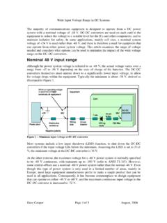
1 Name: Steve Mappus Systems Engineer Date: October 02, 2014 The POWER to Amaze. POWER CONVERTER TOPOLOGY TRENDS , 2 Agenda TOPOLOGY Overview Non Isolated Topologies Isolated DC-DC Derivatives single ended Topologies Transformer Reset Techniques Flyback CONVERTER Forward CONVERTER Double ended Topologies push pull Half Bridge Full Bridge Summary 3 DOUBLE-ENDEDSINGLE-ENDEDACTIVE CLAMP2-SWITCHPUSH-PULLHALF BRIDGEFULL BRIDGELOW POWER (< 100 W)MID- POWER (100 W - 500 W)HIGH- POWER (> 500 W)HARD SWITCHEDZVT/PHASE SHIFTNON-ISOLATEDISOLATEDDVViO=DVViO =11 FORWARDDDVViO =1 single -ENDEDFLYBACKBOOSTBUCK-BOOSTBUCKAC TIVE CLAMP2-SWITCHLLCI solated POWER TOPOLOGY Derivatives 8 Mainstream CONVERTER Topologies Non-Isolated Isolated Bridge Bridge POWER levels numbers for general discussion only. Exceptions aplenty. 4 Other Topologies? Numerous Variations Exist Sepic Cuk Current Fed Buck Tapped Inductors Multiple Outputs Interleaving More?
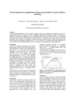
2 Different Ways to Operate Them Voltage Mode Control Current Mode Control Digital Control Variable Frequency CCM, DCM, BCM ZVS ZCS Synchronous Rectification Some Practical CONVERTER TOPOLOGY Advice Most POWER conversion requirements can be met using one or more of the 8 mainstream topologies Save more difficult topologies for unique application requirements Beware of publications proclaiming the best TOPOLOGY 5 Multi-Stage TOPOLOGY Typical Distributed POWER System AC Line85 V < VAC < 265 VVDC = 400 V400 V to 48 V Bus ConverterVPOL_1 < 5 VVPOL_N < 5 V48 V to 12 V IBC (Intermediate Bus CONVERTER )Telecom RectifierHigh POWER DC-DC PFC Boost POLDCDCPFCSYS =% =SYS Scalable, efficient, complex protection functions, sequencing, redundancy, digital control, etc Efficiency example POL DC-DC 6 single -Stage TOPOLOGY PFC Flyback Difficult to meet: Low cost, high PF, low THD, high efficiency, wide VIN with single -stage % AC-DCACEMIPFCFL7733A7 Non-Isolated CONVERTER Topologies 8 Boost CONVERTER (Step Up) VGS(Q)VDS(Q)ILIDS(Q)IDVOUTBCMtONtOFFTS ( ) ( + )= ( ) = ( )= =11 Inductor volt-second balance: Boost CCM transfer function.
3 VIN < VOUT Most efficient at lower D Continuous input current CCM, BCM, DCM modes VOUTVAC VIN(t)DILLVLQCOUTCBYP VOUTVAC VIN(t)DILLVLQCOUTCBYP = ( ) + ( ) =0 9 Operating Mode CCM, BCM or DCM 0 VVDStREStOFFtONTS0 AIL0 VVGSVINVOUT2x(VIN VOUT)tIL(PK) ILTS0 VVDStOFFtON0A0 VVGSVOUTtIL(PK)IL(MIN) ILCCM (Fixed Freq) BCM (Variable Freq) DCM (Fixed Freq) 0 VVDStDtOFFtONTS0 AIL0 VVGStIL(PK) IL VOUTVAC VIN(t)DILLQCOUTCBYPVGSVDS10 Buck CONVERTER (Step Down) VGS(Q)VDVDS(Q)ILIDS(Q)IDVINVFVL-VOUTVIN-VOUTVIN+VFtONtOFFTSI nductor volt-second balance: Buck CCM transfer function: VIN > VOUT Most efficient at higher D VOUT DVOUT DILQLVLLVLQCOUTCOUTVINCINVINCIN =[( ) ] =0 = ( + ) = = = 11 Buck-Boost CONVERTER (Inverting) Inductor volt-second balance: Buck-Boost CCM transfer function: VIN < VOUT or VIN > VOUT Used for negative VOUT = + =0 = ( ) = / / = / ( )/ = 1 -VOUTILLVLQCOUT D-VOUTVINILLVLQCOUTCIN DVINCINVGS(Q)VDS(Q)ILIDS(Q)IDVLVINVINtON tOFFTSVIN+|-VOUT|VOUT-VF-VOUT12 single ended CONVERTER Topologies 13 Benefits of a Transformer ACACDCO utputLoad(or DC)D1 LCOQ1 CINVOVIND1D2 LCONPNSCINQ1 VINVO1.
4 Provides primary to secondary safety isolation subject to regulatory standards 2. Voltage conversion resolution DVVINO=DNNVVPSINO=3. Potential ground differences between primary and secondary Ex: For FSW=300kHz (TSW= s), NP:NS=4:1, 36V<VIN<75 and VO=5V Buck CONVERTER Isolated Buck (Forward) CONVERTER 27% < D < 55% 900 ns < tON < s 6% < D < 14% 200 ns < tON < 467 ns 4. Multiple outputs can be regulated/quasi-regulated 14 Transformer Characteristics NPNSVINVOUTRPRSLP(LEAK)LS(LEAK)CP(W)CS(W )NPNSLMAGRCORECP-S(MUTUAL)NPNSVINVOUTVGS VDS Parasitic Transformer Model CCM Flyback (VDS = 32 V, VLK = 12 V) Overshoot/ringing due to Leakage Inductance Ideal transformer Perfect coupling between Np:Ns No energy storage Flyback transformer Really a coupled inductor Primary energy stored during tON POWER transferred during tOFF 15 single ended Topologies Defined BVt HNI BB1B2+BSAT-BSATD1D2 LCONPNSCINQ1 ResetCircuit(b) Forward CONVERTER single ended Transformer operation limited to first quadrant (c) Gapped Flyback Transformer (a) Forward CONVERTER Transformer Hysteresis DCONPNSCINQ1 VINVO(b) Flyback CONVERTER BVt HNI BB1B2+BSAT-BSATUNGAPPEDGAPPEDRESET CIRCUIT: 1.
5 Third winding 2. RCD reset 3. Resonant reset 4. Active clamp reset 16 Flyback CONVERTER Derivation -VOUTLQCOUT DVINCIN-VOUTLQCOUT DVINCIN1:1-VOUTLMQCOUT DVINCIN1:1(a) (b) (c) (d) (e) a)Non-isolated buck-boost b)Coupled inductor buck-boost c)Isolated buck-boost d)Isolated flyback CONVERTER e)D can be in return path VOUTLMQCOUT DVINCINn:1 VOUTLMQCOUTDVINCINn:1 17 Flyback CONVERTER CCM Operation DDNNVVPSINO =1(a) Flyback CONVERTER (b) CCM Waveforms CCM Transfer Function Limitations Q1 switching loss (hard switched) D2 conduction loss Q1(VDS) > VIN 50% duty cycle limit Right half plane zero in CCM Output rectifier reverse recovery VOUTLMQCOUTDVINCINn:1 NSNP000000 PWMVDSVSIQ1ID1 ILVOUT-(NS/NP)VINVIN+(NP/NS)VOUT18 Quasi-Resonant Flyback Conventional Valley Switching Wide frequency variation depends on output load condition ttiDvDST2 Output POWER [W]fS [Hz]vDSiDttT1 Output load decreasesOperating frequency increasesSOSSLossSwitchingfVCPDS2 19 Quasi-Resonant Flyback Window Valley Switching Tsmax= (a)(b)(c)(d)vDS (100V/div)iD (100mA/div)Time scale 2usec/div Frequency variation depends on output load conditions Operating frequency is within narrow variation ( kHz ~ kHz) Light Load Heavy Load 20 Two-Switch, Quasi-Resonant Flyback CCCVFBFAN6300H12345678 NCHVVDDGATEGNDCSFBDETFAN738212345678 HOVBVSLOCOMLINHINVCCPBIASVINR1R2R3Q1Q2D1 D2D3D4D5 ACINR4C1 VAVLEDVHSC2C3(FROM PFC)(FROM PFC)RDYPBIAS21 Two-Switch Quasi-Resonant Flyback Switching Waveforms 0 VVDS0 AIDStftOFFtONTS0 AIDVA VA0V0 VVDET0 VVINPBIASVIN+VHSVGS(HS)VGS(LS)
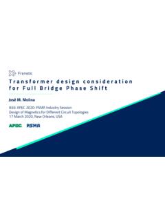
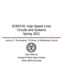
6 OVPIDET(SOURCE)>30 AtDELAY=200nsVRO 2 VRO 2 VIN 2 VIN 2 Quasi-resonant, variable frequency HS and LS MOSFETs switch synchronously Switching period, TS = tOFF + tf + tON Inductor current switches from 0 A (ZCS) every switching cycle VDS ZVS VOUT > 2 VIN Valley switch otherwise Window valley switching 22 Two-Switch Quasi-Resonant Flyback Measured Waveforms Extended Window Valley Switching VOUT < VIN D = 11% FS = 68 kHz POUT = 24 W VDS Valley Switching on First Valley VOUT < VIN D = 42% FS = 63 kHz POUT = 85 W 23 Forward CONVERTER Basics 000 PWMVDS(Q1)VPVR+VINVINIMAG0IQ1 ILID1ID20000 VINRPINRNNVV =D1D2 LCONPNSCINQ1 VINVONRD3 DNNVVPSINO =(a) Forward CONVERTER with Reset Winding (b) DCM Waveforms (D< ) Really a Transformer Coupled Buck CCM Transfer Function Limitations Q1 switching loss (hard switched) D2 conduction loss Q1(VDS) > 2 VIN 50% duty cycle limit (NP:NR = 1:1) 24 Problems with Duty Cycle > 50% VIN0 VPIMAGTSDTSD2 TSD3 TSttRPINNNV Equal Vxt AreaVINVPIMAGttRPINNNV 2TS3 TSTSDTSD2 TSD=67%D=40%Unequal Vxt Area Common practice is to use 1:1 bifilar transformer winding for NP:NR D = 40% CONVERTER operates in DCM Transformer is completely reset on every switching cycle D = 67% CONVERTER wants to operate in CCM Transformer can NOT reset on every switching cycle IMAG increases due to volt second product imbalance Transformer saturation will result Operation beyond D = 50% requires additional reset voltage 25 Duty Cycle Greater Than 50% VDS v s VinThird Winding Reset72849610812013214415616818019220421 636424854606672 Vin (V)VDS (V)Np:NR=1:1Np:NR=1:2 NPNSQ1 NRVDSVINVPIMAGttRPINNNV 2TS3 TSTSDTSD2 TSD=67%Equal Vxt Area}}NP:NR=1:1NP:NR=1:2 For NP:NR = 1:2 VDS=3 VIN Conclusion.
7 Reset winding technique, D > 50% not practical for high VIN applications due to additional MOSFET VDS stress 26 Active Clamp Forward CONVERTER D1D2 LCONPNSCINQ1Q2 CCL0000 PWMQ1 VDSVPIQ1 VINVRESETVIN+VCL0Q2 VGSIMAGICL0IP Advantages Reduced MOSFET VDS voltage stress Higher efficiency through ZVS Use of parasitic elements Higher frequency operation Suitable for off-line (HS clamp) or DC-DC (LS clamp) Disadvantages Conditional ZVS only Dual primary side gate drive with accurate dead-time control and max duty cycle clamp required Poor transient response due to CCL Transfer Function DNNVVPSINO =27 Active Clamp Forward CONVERTER Two Versions D1D2 LCONPNSCINQ1Q2 CCLD1D2 LCONPNSCINQ1Q2 CCL(a)High-Side Active Clamp (Flyback Clamp) (b) Low-Side Active Clamp (Boost Clamp) INVD 11 INVD 11 INVDD 1 INVDD 1 INVDD 1 INVD 11 PARAMETER HIGH-SIDE ACTIVE CLAMP (off-line) LOW-SIDE ACTIVE CLAMP (telecom) VDS VRESET VCL CCL (applied voltage) Lower voltage by VIN volts Highest VCL occurs at DMAX Higher voltage by VIN volts Not practical for off-line CCL (cap value) Same value as low-side for given ripple voltage Same value as high-side for given ripple voltage Clamp MOSFET (Q2) N-Channel Can be used for > 500 V P-Channel Can be used up to 500 V Gate Drive Gate drive transformer required Level shifting gate drive required 28 Active Clamp Forward CONVERTER Zero Voltage Switching (ZVS) ZVS occurs when the voltage across the MOSFET, VDS, is positioned to zero volts prior to the start of the next switching cycle.
8 Benefits of ZVS Reduced switching losses Higher operating frequency possible (smaller passive component size) Higher CONVERTER efficiency Increased reliability Reduced radiated emissions (EMI) VDS ID PSW=VDS x ID x FSW (a) Hard Switching (b) Ideal ZVS 29 Active Clamp Forward CONVERTER Zero Voltage Switching (ZVS) D1D2 LCOQ1Q2 CCLD2 CDSD1 CDSVDSRPRSLP(LEAK)LS(LEAK)CP(W)CS(W)NPNS LMAGRCORECP-S(MUTUAL)CD1CD2 Parasitic elements can be used to benefit ZVS Active Clamp Forward CONVERTER uses fixed frequency resonant transitions to achieve ZVS when specific operating conditions are met 30 single ended (<500W) 2 Switch Forward CONVERTER D1D2 LCONPNSCINQ1Q2D3D4000 PWM(Q1, Q2)VDS(Q1, Q2)VSVIN/NPVINVIN/2ID3, ID4-VIN/NP0IQ1, IQ20 ILID1ID200 IOIMAG0 Advantages Ruggedness MOSFET voltage stress limited to VIN Magnetizing energy recycled by D3, D4 Universal input, 150 W < P < 500 W Disadvantages Limited to less than 50% duty cycle High side gate drive required for Q2 Hard switching Transfer Function DNNVVPSINO =31 single ended (>1kW)
9 Interleaved 2 Switch Forward CONVERTER D1D2 LCONPNSCINQ1Q2D3D4D5D6 LNPNSQ3Q4D7D8 DnDnLNPNSQnQnDnDn Advantages Can operate multiple POWER stages out of phase Ripple current cancellation at output capacitor Reduced RMS current at input capacitor Multiple stages can add up to kW of POWER Smaller output inductors can improve transient response Disadvantages Design complexity PCB layout can be challenging 32 Double ended CONVERTER Topologies 33 Double ended Topologies Defined BVt+BSAT HNI-BSAT BB1B2 BVt HNI BB1B2+BSAT-BSAT BB1B2(RCD Reset)(Active Clamp)NormalFlux ImbalanceSaturationPrimary CurrentDouble ended Transformer operation occurs in first and third quadrants Active Clamp Forward single ended but operates slightly into the third quadrant Half-Bridge, Full-Bridge Symmetrical operation between first and third quadrants No transformer reset circuitry required 34 Double ended (<500 W) Half Bridge CONVERTER (Symmetrical) D1D2 LCONPNSQ1 NSQ2 CINC1C2 VPVDS(Q1, Q3)VINVDS(Q2, Q4)
10 VINID1ID2 ILIOVPIPVIN/2 PWM, Q1 PWM, Q2-VIN/2 Advantages Better transformer utilization MOSFET voltage stress limited to VIN Best for high VIN off line applications up to 500W single winding primary Transformer balanced by C1 and C2 Asymmetric and resonant versions can ZVS Disadvantages Totem pole primary gate drive High primary current Possible cross conduction between Q1 and Q2 Hard switching Transfer Function DNNVVPSINO =235 Asymmetrical Half Bridge CONVERTER +Vp-+Vd-+Vp-1 : 10 Asymmetric square waveformSymmetric square waveformVdVd0CB+Vp-+Vd-+ VCB -Same areaVCB+Vp-1 : 100 What if an asymmetric square wave is introduced to the transformer? Transformer will be saturated What if an asymmetric square wave is introduced to the transformer in series with a DC blocking capacitor? Not saturated due to the voltage of the blocking capacitor, CB 36 Asymmetrical Half Bridge CONVERTER VPIPQ2 (D)Q1 (D)VIN/2-VIN/2D= (D)Q1 (1-D)VIN-VCBVCBVCBD= AreaVIN-VCB(a) Symmetrical HB waveforms (b) Asymmetrical HB waveforms Asymmetrical Gate Drive Q2 modulated by D Q1 driven by 1-D Fixed dead time between Q1 and Q2 Dead time optimized for ZVS and anti cross conduction Fixed frequency ZVS PWM operation Near D= , operation is same as symmetrical HB BUT, excessive voltage stress is applied to secondary rectifier at VIN(MAX) ()DDNNVVPSINO =12D1D2 LCONPNSQ1 NSQ2 CINCBVP37 Asymmetrical Half Bridge CONVERTER ()DVVOD =12 ODVDV =1 Secondary rectifier voltage stress: Reverse recovery and parasitic ringing Wide D range requires use of high voltage rectifiers CONVERTER operates best near D = 0 5 10 15 20 25 30 35 40