Transcription of Power GenerationDistribution and Substation …
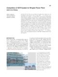
1 Hitachi Review Vol. 63 (2014), No. 4 167. Power Generation, Distribution and Substation system for development of offshore Wind Farms Shinzo Inoue OVERVIEW: With use of renewable energy growing worldwide, wind Tatsuji Ishibashi Power generation in particular is expected to play a major role, having a Takashi Matsunobu comparatively low per-kilowatt cost. While most wind Power generation in Japan to date has been land-based, an expansion is anticipated in the development of offshore sites, which offer more reliable and stronger wind conditions. Hitachi has developed a large 5-MW downwind wind Power generation system for the construction of offshore wind farms, and supplies total solutions that extend from generation to Power delivery, including Substation and transmission systems. INTRODUCTION This article gives an overview of a large 5-MW. RECENT years have seen growing interest in downwind wind Power generation system designed for renewable energy in Japan because of its potential use in offshore wind farms, and describes Substation to help protect the global environment and provide and distribution systems for such wind farms.
2 A domestic source of energy. Prompted by the introduction of feed-in tariffs for renewable energy LARGE 5-MW offshore WIND Power . in July 2012, Japan has seen steady progress on GENERATION system . developments in this field, including of wind Power Features of Downwind Wind Power Generation generation. system While most of the wind Power generation Fig. 1 shows the overall dimensions of the large systems currently operating in Japan are land-based, wind Power generation system with offshore sites are seen as having great potential, with a rated output of 5 MW that is currently under advantages that include stronger wind conditions development . Fig. 2 shows the design Power curve and being less likely to raise concerns such as noise and Table 1 lists the main specifications. or impact on the scenery. According to the Report Like the existing 2-MW wind Power on FY2010 Study of Potential for Introduction of generation system , this new model has a downwind Renewable Energy (1) published by the Ministry of configuration.
3 Most large wind turbines have an the Environment, there is the potential in Japan for the installation of as much as 1,570 GW of offshore wind Power . This is roughly eight times the GW total installed capacity of Japan's ten Power Wind direction companies in FY2009(2). While the construction of an offshore wind farm Rotor diameter: Hub typically requires a greater investment than a land- 126 m based site, a large part of this is due to the foundations being larger and more complex than on land, and also Nacelle due to the offshore installation work and transmission Tower height: system , including undersea cable. Accordingly, to 90 m improve the economics of offshore wind farms, it is Tower better to increase the output per turbine so that the total number of installed turbines can be reduced. This requires wind Power generation systems that are larger Fig. 1 Overall Dimensions of than the 2- to 3-MW-class turbines that are considered The large wind Power generation system has a large by land-based standards.
4 Rated capacity of 5 MW. Power Generation, Distribution and Substation system for development of offshore Wind Farms 168. TABLE 1. Main Specifications 6,000 Like the 2-MW , the has a downwind 5,000 configuration. 4,000 Output (kW). (for reference). 3,000. Rated output 5,000 kW 2,000 kW. 2,000 Rotor orientation Downwind Downwind 1,000 Rotor diameter 126 m 80 m 0 Hub height 90 m 65 m/80 m 0 10 20 30 Output control Pitch, variable speed Pitch, variable speed Wind speed (m/s) Yaw control Active yaw Active yaw Idling in strong winds Free yaw Free yaw Fig. 2 Design Power Curve. 1:100 (approx.) (50 Hz). Gear ratio 1:40 (approx.). The design Power curve of the 1:120 (approx.) (60 Hz). Permanent magnet Doubly fed induction Generator synchronous generator (4-pole). generator (36-pole). upwind configuration, meaning the rotor is upwind Cut-in wind speed 4 m/s 4 m/s of the tower. However, in situations such as when Cut-out wind speed 25 m/s 25 m/s an outage caused by a grid fault coincides with a Wind speed class S (10 m/s mean IIA+.)
5 Annual wind speed). sudden change in wind direction, for example, the overturning moment experienced by a downwind turbine is lower because it can immediately switch Blade wake Blade wake to free yaw operation in which the nacelle naturally turbulence turbulence orients itself along the direction of the wind. This Anemometer Anemometer should reduce construction costs by simplifying the turbine foundations throughout the wind farm. Also, wind turbines are fitted with an anemometer for yaw control. Whereas upwind turbines typically mount this anemometer downwind of the rotor, the ability to have the anemometer upwind of the rotor in a downwind turbine minimizes the influence of blade Upwind wind turbine Downwind wind turbine wake turbulence and reduces loss of generation due Fig. 3 Location of Anemometer and Relationship with Blade to yaw error (see Fig. 3). Wake. Another consequence of having the rotor on the Because the anemometer on a downwind wind turbine can be downwind side is that, during strong winds, rising located upwind of the rotor, it suffers less interference due to wind speeds tend to increase the clearance between the blade wake turbulence.
6 Blades and tower. This is a safety advantage because it reduces the risk of the blades coming into contact with the tower, in contrast to an upwind turbine where higher wind speeds reduce the clearance between the blades and tower (see Fig. 4). Reduces clearance Increases clearance between the blades between the blades Equipment Configuration of Large 5-MW Wind and tower and tower Turbine Fig. 5 shows the equipment layout in the nacelle of the large 5-MW wind turbine. Large wind turbines typically use variable-speed operation in which the Upwind wind turbine Downwind wind turbine speed of rotation is varied to keep the tip speed ratio ( ) constant with changes in wind speed (see Fig. 6). Fig. 4 Clearance between the Blades and Tower during High Because the tip speed ratio for a particular blade shape Winds. needs to be kept the same regardless of turbine size, With a downwind configuration, the clearance between the this means that, under the same wind speed conditions, blades and tower increases during high winds, reducing the the angular velocity needs to be reduced as the rotor potential for the blades and tower to come into contact.
7 Hitachi Review Vol. 63 (2014), No. 4 169. Rotor radius (R). Hub Wind Frame speed ( ) Rotor angular velocity ( ). Gearbox Generator Tip speed ratio: = R / . Yaw drive mechanism Nacelle control panel Radiator cooler Fig. 6 Wind Turbine Tip Speed Ratio. Wind turbines typically use variable-speed operation whereby the tip speed ratio ( ) is kept constant as the wind speed varies. Fig. 5 Equipment Layout in Nacelle. The equipment inside the large 5-MW wind turbine is laid out as shown. Wind Power generator Grid connection diameter becomes larger(3). Accordingly, to keep the speed of the input shaft to the generator constant, Electric Power a higher gear ratio is needed as the rotor diameter distribution Transmission and becomes larger, increasing the potential for gearbox distribution equipment problems. Hitachi has minimized this potential for Substation building Grid monitoring Undersea cable gearbox problems by adopting a medium-speed gear Cable drive system that combines a 36-pole permanent Cable laying magnet synchronous generator with a gearbox that has a gear ratio of no more than about 1:40.
8 Fig. 7 Overview of Electric Power Distribution Equipment. The electric Power generated by the wind turbines is transmitted to a land-based grid connection Substation via array cables and ELECTRIC Power DISTRIBUTION AND export cables. Substation EQUIPMENT. Fig. 7 shows the electric Power distribution equipment for linking wind turbines to the existing used to connect to the grid. The voltage of the Power grid that is intended for use with the 5-MW offshore generated by the wind turbines is stepped up by two wind Power generation system . The electric Power transformers and connected to an existing trunk generated by the wind turbine is transmitted to an transmission line. As the capacity factor of offshore onshore grid connection Substation via a Power cable wind Power generators has been estimated at 50% or that connects to a number of generators (array cable) less(4), a redundant configuration is used so that, if one and a cable that carries the electric Power to land of the transformers fails, operation can continue using (export cable).
9 At the grid connection Substation , a the remaining functional transformer. To improve transformer steps up the voltage to the grid voltage reliability, an active/backup configuration is also used and the Power is supplied to the grid via a connection for the connection to the existing transmission line. point. The following sections describe the Substation In addition to performing grid analyses of voltage equipment and undersea cable used by this system . fluctuations and other factors for grid connections, detailed protection coordination is also implemented Substation from the grid-side to the wind turbines. Hitachi has many years of multi-faceted experience Hitachi is also designing the Substation equipment with ultra-high-voltage switchgear, Power system itself to be more compact and place less of a load on the analysis, equipment protection and control, and with environment.
10 One example is the use of an integrated static var compensators (SVC), and high-voltage three-phase bus in 275-kV gas-insulated switchgear direct current (HVDC) Substation equipment. This (GIS) to reduce both its installation footprint and the technology and know-how is available for use in grid amount of sulfur hexafluoride (SF6) insulating gas connection substations for offshore wind farms. Fig. 8 used. Also, Hitachi's 33-kV circuit breaker (package shows a connection diagram for Substation equipment GIS) uses a T-shaped cable head. A feature of this Power Generation, Distribution and Substation system for development of offshore Wind Farms 170. the case of strong currents, deep locations, or rocky or Transmission Transmission line protection line protection broken seafloor terrain(5), (6). relay ( Power relay (other company) users) Although cross-linked polyethylene (XLPE), which has low losses, is widely used as cable insulation in Transmission Japan, it has problems with long-term exposure to water line protection relay such as the formation of water trees.

