Transcription of Power MOSFET - Vishay Intertechnology
1 Document Number: 91291 B, 21-Mar-111 This datasheet is subject to change without PRODUCT DESCRIBED HEREIN AND THIS DATASHEET ARE SUBJECT TO SPECIFIC DISCLAIMERS, SET FORTH AT MOSFETIRFZ44, SiHFZ44 Vishay Siliconix FEATURES Dynamic dV/dt Rating 175 C Operating Temperature Fast Switching Ease of Paralleling Simple Drive Requirements Compliant to RoHS Directive 2002/95/ECDESCRIPTIONT hird generation Power MOSFETs from Vishay provide thedesigner with the best combination of fast switching,ruggedized device design, low on-resistance TO-220AB package is universially preferred forcommercial-industrial applications at Power dissipationlevels to approximately 50 W.
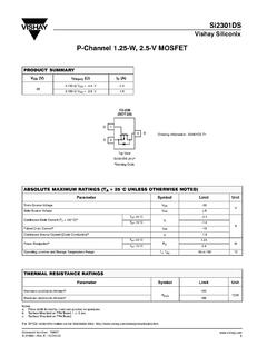
2 The low thermal resistanceand low package cost of the TO-220AB contribute to itswide acceptance throughout the Repetitive rating; pulse width limited by maximum junction temperature (see fig. 11).b. VDD = 25 V, starting TJ = 25 C, L = 44 H, Rg = 25 , IAS = 51 A (see fig. 12).c. ISD 51 A, dI/dt 250 A/ s, VDD VDS, TJ 175 mm from Current limited by the package, (die current = 51 A).PRODUCT SUMMARYVDS (V)60 RDS(on) ( )VGS = 10 V (Max.) (nC)67 Qgs (nC)18 Qgd (nC)25 ConfigurationSingleN-Channel MOSFET GDSTO-220 ABGDSA vailableRoHS*COMPLIANTORDERING INFORMATIONP ackageTO-220 ABLead (Pb)-freeIRFZ44 PbFSiHFZ44-E3 SnPbIRFZ44 SiHFZ44 ABSOLUTE MAXIMUM RATINGS (TC = 25 C, unless otherwise noted)PARAMETER SYMBOLLIMITUNITD rain-Source Voltage VDS60V Gate-Source VoltageVGS 20 Continuous Drain CurrenteVGS at 10 VTC = 25 C ID50 AContinuous Drain CurrentTC = 100 C 36 Pulsed Drain CurrentaIDM 200 Linear Derating C Single Pulse Avalanche EnergybEAS 100mJ Maximum Power DissipationTC = 25 C PD150W Peak Diode Recovery dV/dtcdV/dt Operating Junction and Storage Temperature RangeTJ, Tstg- 55 to + 175 C Soldering Recommendations (Peak Temperature)
3 Dfor 10 s300 Mounting Torque6-32 or M3 screw10lbf m* Pb containing terminations are not RoHS compliant, exemptions may apply Document Number: 912912S11-0517-Rev. B, 21-Mar-11 This datasheet is subject to change without PRODUCT DESCRIBED HEREIN AND THIS DATASHEET ARE SUBJECT TO SPECIFIC DISCLAIMERS, SET FORTH AT , SiHFZ44 Vishay Siliconix Notesa. Repetitive rating; pulse width limited by maximum junction temperature (see fig. 11).b. Pulse width 300 s; duty cycle 2 %.THERMAL RESISTANCE RATINGSPARAMETER Junction-to-AmbientRthJA-62 C/WCase-to-Sink, Flat, Greased Junction-to-Case (Drain) (TJ = 25 C, unless otherwise noted)PARAMETER SYMBOLTEST CONDITIONS Breakdown Voltage VDS VGS = 0 V, ID = 250 A 60--V VDS Temperature Coefficient VDS/TJ Reference to 25 C, ID = 1 mA C Gate-Source Threshold Voltage VGS(th)VDS = VGS, ID = 250 A Gate-Source Leakage IGSS VGS = 20 V-- 100nA Zero Gate Voltage Drain Current IDSS VDS = 60 V, VGS = 0 V --25 A VDS = 48 V, VGS = 0 V, TJ = 125 C --250 Drain-Source On-State Resistance RDS(on)
4 VGS = 10 VID = 31 Forward Transconductance gfsVDS = 25 V, ID = 31 A15--S DynamicInput Capacitance Ciss VGS = 0 V, VDS = 25 V,f = MHz, see fig. 5 -1900-pFOutput Capacitance Coss -920-Reverse Transfer Capacitance Crss -170-Total Gate Charge Qg VGS = 10 V ID = 51 A, VDS = 48 V, see fig. 6 and 13b--67nC Gate-Source Charge Qgs --18 Gate-Drain ChargeQgd --25 Turn-On Delay Time td(on) VDD = 30 V, ID = 51 A, Rg = , RD = , see fig. 10b-14-nsRise Timetr -110-Turn-Off Delay Time td(off) -45-Fall Time tf -92-Internal Drain Inductance LD Between lead,6 mm ( ") from package and center of die contact Internal Source Body Diode CharacteristicsContinuous Source-Drain Diode Current ISMOSFET symbolshowing the integral reversep - n junction diode--50 APulsed Diode Forward CurrentaISM--200 Body Diode VoltageVSDTJ = 25 C, IS = 51 A, VGS = 0 Diode Reverse Recovery TimetrrTJ = 25 C, IF = 51 A, dI/dt = 100 A/ s-120180nsBody Diode Reverse Recovery Turn-On TimetonIntrinsic turn-on time is negligible (turn-on is dominated by LS and LD)
5 DSGSDG Document Number: 91291 B, 21-Mar-113 This datasheet is subject to change without PRODUCT DESCRIBED HEREIN AND THIS DATASHEET ARE SUBJECT TO SPECIFIC DISCLAIMERS, SET FORTH AT , SiHFZ44 Vishay Siliconix TYPICAL CHARACTERISTICS (25 C, unless otherwise noted)Fig. 1 Typical Output Characteristics, TC = 25 CFig. 2 - Typical Output Characteristics, TC = 175 CFig. 3 - Typical Transfer CharacteristicsFig. 4 - Normalized On-Resistance vs. Temperature Document Number: 912914S11-0517-Rev. B, 21-Mar-11 This datasheet is subject to change without PRODUCT DESCRIBED HEREIN AND THIS DATASHEET ARE SUBJECT TO SPECIFIC DISCLAIMERS, SET FORTH AT , SiHFZ44 Vishay Siliconix Fig.
6 5 - Typical Capacitance vs. Drain-to-Source VoltageFig. 6 - Typical Gate Charge vs. Gate-to-Source VoltageFig. 7 - Typical Source-Drain Diode Forward VoltageFig. 8 - Maximum Safe Operating Area Document Number: 91291 B, 21-Mar-115 This datasheet is subject to change without PRODUCT DESCRIBED HEREIN AND THIS DATASHEET ARE SUBJECT TO SPECIFIC DISCLAIMERS, SET FORTH AT , SiHFZ44 Vishay Siliconix Fig. 9 - Maximum Drain Current vs. Case TemperatureFig. 10a - Switching Time Test CircuitFig. 10b - Switching Time Waveforms Fig. 11 - Maximum Effective Transient Thermal Impedance, Junction-to-CaseFig. 12a - Unclamped Inductive Test CircuitFig. 12b - Unclamped Inductive WaveformsPulse width 1 sDuty factor % V+-VDSVDDVDS90 %10 %VGStd(on)trtd(off) +-VDD10 VVar y tp to obtainrequired IASIASVDSVDDVDStp Document Number: 912916S11-0517-Rev.
7 B, 21-Mar-11 This datasheet is subject to change without PRODUCT DESCRIBED HEREIN AND THIS DATASHEET ARE SUBJECT TO SPECIFIC DISCLAIMERS, SET FORTH AT , SiHFZ44 Vishay Siliconix Fig. 12c - Maximum Avalanche Energy vs. Drain CurrentFig. 13a - Basic Gate Charge WaveformFig. 13b - Gate Charge TestQGSQGDQGVGC harge10 F50 k 12 VCurrent regulatorCurrent sampling resistorsSame type as +- Document Number: 91291 B, 21-Mar-117 This datasheet is subject to change without PRODUCT DESCRIBED HEREIN AND THIS DATASHEET ARE SUBJECT TO SPECIFIC DISCLAIMERS, SET FORTH AT , SiHFZ44 Vishay Siliconix Fig. 14 - For N-ChannelVishay Siliconix maintains worldwide manufacturing capability.
8 Products may be manufactured at one of several qualified locations. Reliability data for SiliconTechnology and Package Reliability represent a composite of all qualified locations. For related documents such as package/tape drawings, part marking, andreliability data, see recoverydV/dtRipple 5 %Body diode forward dropRe-appliedvoltageReverserecoverycurr entBody diode forwardcurrentVGS = 10 Va ISDD river gate lSD VDS waveformInductor currentD = +-+++---Peak Diode Recovery dV/dt Test CircuitVDD dV/dt controlled by Rg Driver same type as ISD controlled by duty factor D - device under layout considerations Low stray inductance Ground plane Low leakage inductancecurrent transformerRgNotea. VGS = 5 V for logic level devicesVDDP ackage Siliconix Revison: 14-Dec-151 Document Number: 66542 For technical questions, contact: DOCUMENT IS SUBJECT TO CHANGE WITHOUT notice .
9 THE PRODUCTS DESCRIBED HEREIN AND THIS DOCUMENTARE SUBJECT TO SPECIFIC DISCLAIMERS, SET FORTH AT M* = inches to inches (dimension includingprotrusion), heatsink hole for HVMM*321LL(1)DH(1)Q PAFJ(1)b(1)e(1) (1) (1) (1) (1) (1) : X15-0364-Rev. C, 14-Dec-15 DWG: 6031 Package PictureASEXi anLegal disclaimer Revision: 09-Jul-20211 Document Number: 91000 disclaimer ALL PRODUCT, PRODUCT SPECIFICATIONS AND DATA ARE SUBJECT TO CHANGE WITHOUT notice TO IMPROVE RELIABILITY, FUNCTION OR DESIGN OR OTHERWISE. Vishay Intertechnology , Inc., its affiliates, agents, and employees, and all persons acting on its or their behalf (collectively, Vishay ), disclaim any and all liability for any errors, inaccuracies or incompleteness contained in any datasheet or in any other disclosure relating to any makes no warranty, representation or guarantee regarding the suitability of the products for any particular purpose or the continuing production of any product.
10 To the maximum extent permitted by applicable law, Vishay disclaims (i) any and all liability arising out of the application or use of any product, (ii) any and all liability, including without limitation special, consequential or incidental damages, and (iii) any and all implied warranties, including warranties of fitness for particular purpose, non-infringement and regarding the suitability of products for certain types of applications are based on Vishay 's knowledge of typical requirements that are often placed on Vishay products in generic applications. Such statements are not binding statements about the suitability of products for a particular application. It is the customer's responsibility to validate that a particular product with the properties described in the product specification is suitable for use in a particular application.