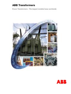
Transcription of Power Transformer Protection
1 A GO3-5005 EMarch 1988 Power Transformer ProtectionApplication GuideAuthorR NylenSenior application engineer)ABB RelaysPower Transformer protectionAGO3-5005 EPage 2 List of contents)1. INTRODUCTION2. CONDITlONS LEADING TO FAUL Insulation Aging of Overheating due to Oil contamination and Reduced cooling3. FAULT Ground faults in a solidly groundedstar-connected secondary Ground faults in a high impedancegrounded star-connectedsecondary Ground faults in a Turn-to-turn Phase-to-phase faults4. PROTECTIVE RELA Differential Differential relays for fully Differential relays for Overcurrent Protection andimpedance Time-overcurrent Under-impedance Distance Grou~d fault Low irrnpedance residualovercurrent Harmonic restraint High impedance restricted Low impedance restricted Tank Residual voltage Overexcitation Flashover and ground faultprotections for low voltage Systems without rectifiers orfrequency Systems with rectifiers andfrequency converters withoutpulse' Systems with rectifiers and pulse-width-modulated frequencyconverters5.
2 Gener, Gas d~tector Temperature PresslUre relay for on-load PresslUre relief Oil level Silica gel dehydrating breather6. SUMMARY7. REFERENCESList of illustrationsFig. relay used as atransfQrmer of ground faultoverclilrrent ~ction of arestricted groundfault relay for a of arestricted groundfault relay for a D-connectedwinding and agroundingtransf<i> differential andrestricted ground fault relays on thesame CT fault ~d fault and flashover short fault current in a solidlygrounded Y-connected fault current in a highimpedance grounded inrush inrush current for a 60MV A Transformer 140/40 faun current differential relay relay RADHA or RADSGfor RelaysPower Transformer protectionAGO3-5005 EPage prevent faults and to minimize the
3 Damagein case ot a fault, transformers are equippedwith both protective relays and monitors. Thechoice af protective equipment variesdepending, on Transformer size, voltage level, RELA VS is the largest manutacturer ofprotective relays in the world, leading thedevelopm~nt of relays with relays are built up in a modularizedplug-in system called COMBIFLEX@, a sys-tem characterized by great flexibility and re-Iiability. Tl11e relays in the COMBIFLEX sys-tem have l:iJeen optimized with respect to theirquaiity, dimension and COMBIFLEX relays can be tested by atest system called COMBITEST by plugging atest-handla inta a built-in test switch.
4 Bythis it is possible to carry out a sate and easyinjection test of a relay. The road currentthrough a relay in service can be measuredby an ammeter connected to a current mea-suring plug with a built-in overvoltage pro-tection. If the am meter circuit is open bymistake the plug will be short-circuited bythe overvoltage Protection . By this the currentin a CT -cirrcuit can be measured without anyrisk of getling an open CT -circuit. A veryimportant safety Power Transformer is a very valuable andvitallink in a Power transmission system. Highreliability of the Transformer is thereforeessentiai to avoid disturbances in trans-mission of high quaiity Transformer properly designedand supplied with suitable protective relaysand monitors is very reliable.
5 Less than onefault in 100 Transformer years can a fault occurs in a Transformer , thedamage is normal ly severe. The transformerhas to be transported to a workshop andrepaired, which takes considerable time. Tooperate a Power transmission system with atransformer out of service is always , the impact of a Transformer fault ismore serious than a transmission line operation and maintenance of atransformer can be a contributory cause of afault. If a Transformer is operated at too hightemperature, too high voltage, or exposed toan excessive number of high current externalfaults etc, the insulation can weaken to thepoint of tap-changers should be checkedand maintained according to the operatinginstructions to prevent any faults.
6 A fault in atap-changer with a separate housing cancause too high a pressure in the housing. Apressure relay can be used to trip the circuitbreakers at a certain set pressure, seepoint TO of insulationAging or deterioration of insulation is afunction of time and temperature. The part ofthe windin~ which is operated at the highesttemperature (hot-spot) will ordinarilyundergo the greatest deterioration and getsthe shorte$t length of life. However, it is notpossible tO! accurately predict the length of lifeas a functibn of temperature and time underconstant Gontrolled conditions, much lessunder widely varying service case a Transformer gets too hot, Improvethe cooling if possible or reduce the load inorder to avoid accelerated aging of theinsulation.
7 A temporary moderate over-temperature can be allowed as it takes aconsiderablle time to age the breakdownA breakdown of the insulation results in shortcircuits or ground faults, frequently causingsevere damage to the windings and thetransformer core. Furthermore, a high gaspressure may develop, damaging the trans-former of the insulation between windingsor between windings and the core can becaused by:.aging of insulation due to overtempe-rature during long discharges in the overvoltages due to thunder-storms or switching in the forces on the windings due toexternal faults with high flash-over between the primary and se-condary windings usually results in a break-down of the insulation between the secondarywinding and RelaysPower Transformer protectionAGO3-5005 EPage contaminatipn and leakageThe oil in a Transformer constitutes an elect-rically insulating medium and also a coolingmedium.
8 The service reliability of an oil-immersed Transformer therefore depends to agreat extent on the quaiity of the oil. The oilshould fulfill the l1equirements of lEG dielectric sttength of the oil is the mostimportant propert y of the oi!. If the dielectricstrength of the <Dil is reduced by water andimpurities etc, a breakdown of the insulationcan occur. Testing of the dielectric strength ofthe oil is normally conducted on site to get aquick check of the purity of the oillevel must be monitored, a breakdownof the insulation occurs if the oil level gets immersed transformers with an oilconservator should therefore be provided withboth a silica gel breather and an oil coolingForced cooling systems must be an alarm sh all be given if the coolingsystem stops.
9 The oil temperature can thenbe watched and appropriate action takenbefore the Transformer becomes due to overexcitationAccording to lEG 76-1 guidelines, trans-i formers shall be capable of delivering ratedi currents at an applied voltage equal to 105%lot the rated voltage. Transformers may be!specified for operation at a voltage up to110% of rated a Transformer is operated at too highvoltage or at too low frequency, theItransformer core gets overexcited. The flux isthen forced through surrounding steel partssuch as the sheet metal of the tank and otherlunlaminated parts of the Transformer . Theseiparts are heated up in an unacceptable wayand the Transformer can be damaged.
10 As atransformer loaded with rated current canwithstand on ly 105% of rated voltagecontinuously, the Transformer has to bedisconnected if the voltage is too high or thefrequency too low. According to IEEE generalguide for permissible short-time over-excitation of Power transformers, see tig 1,transformers can only with stand overex-citation a short turbo-generator Transformer unitscan be exposed to overvoltage and under-frequency conditions. They should beprovided with an overexcitation relay opera-ting when the ratio between voltage andrrequency (V/Hz) gets too get a correct representation of the flux, theoverexcitation relays must be connected to apotential Transformer , measuring the voltage?