Transcription of PowerBar Insulated Conductor Bar Systems - hubbellcdn
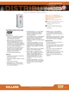
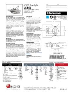
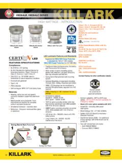
1 PowerBarInsulated Conductor Bar Systems600 VOLTS - , 250 VOLTS HUBBELL COMPANY INVERTED V-BAR - for new applications The inverted V shape of the Conductor bar provides more overall strength The inverted V collector contact surface keeps the contact shoes centered for improved collector tracking and more uniform brush wearUNIVERSAL 8-BAR - to match existing Systems Nylon hangers provide for double insulation against electrical groundingLR-59861 Gleason Reel Corp. 600 S. Clark St, Mayville, WI 53050 PH: 920-387-4120 | FAX: 920-387-4189 1911, Gleason Reel Corporation has been in the business of CABLE & HOSE MANAGEMENT. Our products are designed to convey and protect valuable cables and hoses that power and control moving machines of all types. They improve productivity and safety on the job by moving cables and hoses away from hazardous locations on machinery or the shop floor into a controlled environment. Whether you choose Reels for efficient storage and payout from virtually any angle, Festoon or Conductor Bar Systems for overhead applications or PowerTrak for protection on machinery in motion, your cables/hoses will last longer and provide better service with a cable management system from GLEASON REEL CORPORATION - A HUBBELL PROFILEAPPLICATION PHOTOS Insulated Conductor BAR system - INVERTED V-BARSHOWN IN OVERHEAD CRANE APPLICATION DESIGN & CONSTRUCTIONCONDUCTOR BARS:All INVERTED V-BAR and UNIVERSAL 8-BAR Conductor bar sections are roll formed from galvanized steel or electrolytic copper.
2 These Systems are amply sized and proportioned to carry the specified current without overheating. Internal joint connections assure full current carrying capacity without interfering with the free travel of the sliding collector contact shoes. The standard insulating cover has a maximum temperature rating of 163 F (73 C). Conductor JOINTS:The joints for these Systems consist of two connector pins made of plated steel for the galvanize steel Conductor bar or electrolytic copper for the copper Conductor bar. The connector pins are knurled to provide sufficient current carrying capacity and mechanical strength. The joint is designed to automatically align the Conductor bar sections during SUPPORTS:The standard hangers are a snap-in design made from nylon or polycarbonate. The maximum temperature rating is 400 F (204 C). Anchor hangers are available to control the movement of the Conductor bar.
3 They must be used on Systems less than 30 feet long., at all transfer sections and runs to control expansion and contraction flow. Conductor COLLECTORS:Collector assemblies are offered in either single or double shoes types providing a continuous current carrying capacity of 40 amperes to 200 amperes. The contact shoes are supported by an insulating support that is spring loaded by an arm and body mechanism. All collectors are supplied with copper/graphite contacts for speeds up to 900 feet per minute on the INVERTED V-BAR and UNIVERSAL 8-BAR Systems . For faster travel speeds, consult the factory. NOTE: Current ratings are based on ambient temperature of 86 F (30 C).The INVERTED V-BAR Systems offer superior collector tracking capabilities especially at higher speeds since the V shaped metal guides the collector contact shoes rather than the insulating cover as with all 8-Bar INVERTED V-BAR Systems can be mounted for bottom entry or side entry of the collector contact V-BAR Systems are recommended for side entry (lateral mounted) Systems over 8-Bar Systems or Systems with flat contact surfaces.
4 Counter-balanced collectors are not required with the INVERTED V-BAR Systems . The inward spring pressure on the contact shoe against the metal V contact surface fights off the downward gravitational pull to provide more uniform contact show wear. The UNIVERSAL 8-BAR Systems may be used interchangeably with other 1 bottom entry 8-bar Systems . ADVANTAGESThe Conductor Electrification system shall consist of thermoplastic enclosed Conductor bar with mechanically tensioned collectors as manufactured by Gleason Reel Systems shall have a voltage rating of ( ) Volts or ( ) Volts and have a continuous current capacity of ( ) Amperes per pole. When used as a Crane and Hoist Electrification system , the system shall be rated at ( ) Amperes for continuous service and ( ) Amperes for intermittent service. The full current carrying capacity of the system shall be maintained system shall permit longitude movement of the Conductor bars in order to allow for unequal thermal expansion and contraction.
5 The system shall consist of standardized, interchangeable Conductor bars (sections), power feeds, end caps, joint covers and collectors as called for in the plans. TYPICAL SPECIFICATIONSP olycarbonate snap-in hangers provide an extra level of insulation as well as a rigid support for the Conductor APPLICATIONS: Overhead Cranes Monorails Traveling Robots Aircraft Hanger Doors AS/RS Systems The sections shall be made from roll formed galvanized steel or electrolytic copper and shall have a continuous V - groove, in the center, running the entire length. Conductors of this design shall be capable of carrying a current of 90 amperes and 110 amperes for steel sections and 250 amperes for copper sections continuously without overheating. The sections shall be Insulated with a thermoplastic cover rated for ambient temperatures to 163 F (73 C).The type of the Conductor will be either 8-Bar or V-Bar configurations as called for in the collectors shall consist of a lubricant impregnated contact shoe, mechanically supported by an insulating support assembly that is spring loaded by an arm and body mechanism.
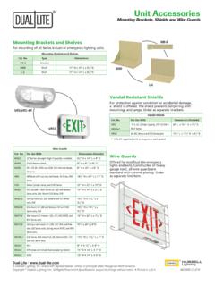
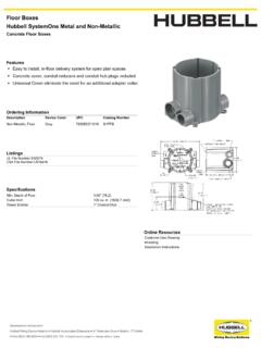
6 Collector assemblies shall be mounted on a 1 square mounting post and allow for 3 collector spacing without staggering. The collector contact shoes shall have the unique concave shape for 8-Bar Systems or an inverted V shape for V-Bar Systems . 3 Conductor SECTIONSFOR 90, 110 OR 250 AMP SYSTEMSSPECIAL APPLICATIONSC onsult the factory for information and pricing on the following:1. Curved Conductor sections2. Corrosion resistant - stainless steel conductors are availableCONDUCTOR SECTIONSC omplete 10 (3028mm) long sections include two knurled connector pins and 163 F (73 C) rated thermoplastic insulating cover. 4 CATALOG CURRENT RATINGINTERMITTENT CURRENT RATINGCONDUCTOR MATERIAL LENGTHftWEIGHTlbsV-90A90 Ampere135 AmpereGalv. Steel10 (3048mm) ( kg) V-110A110 Ampere165 AmpereGalv. Steel10 (3048mm) ( kg) V-250AL250 Ampere375 AmpereCopper / Steel10 (3048mm) ( kg) INVERTED V-BARCATALOG CURRENT RATINGINTERMITTENT CURRENT RATINGCONDUCTOR MATERIAL LENGTHftWEIGHTlbs8-90A90 Ampere135 AmpereGalv.
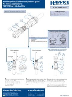
7 Steel10 (3048mm) ( kg) 8-110A110 Ampere165 AmpereGalv. Steel10 (3048mm) ( kg) 8-250AL250 Ampere375 AmpereCopper / Steel10 (3048mm) ( kg) UNIVERSAL 8-BARCONDUCTOR SECTIONSFOR 90, 110 OR 250 AMP SYSTEMSCONDUCTION SUPPORTST hermoplastic snap-in type hangers and anchor hangers provide for an additional level of insulation as well as rigid support. of the Conductor anchor hanger should be used on Systems less than 30 (9m) in length, at all transfer points/interlocks and where the Conductor movement must be controlled or restricted. Steel type hangers are also if the system is to be Side Entry (Lateral Mount) or Bottom Entry (Vertical Mount) and consult the Mounting Table (Right).NOTE:Expansion sections must be staggered when Conductor spacing is less than 3 (76mm).*V-BAR is recommended on all Side Entry CURRENT RATINGINTERMITTENT CURRENT RATINGCONDUCTOR MATERIAL LENGTHftWEIGHTlbsV-BAR8-BARV-90E8-90E90 Ampere135 AmpereGalv.
8 Steel10 (3048mm) ( kg) V-110E8-110E110 Ampere165 AmpereGalv. Steel10 (3048mm) ( kg) V-250EL8-250EL250 Ampere375 AmpereCopper / Steel10 (3048mm) ( kg)SYSTEMMOUNTINGV-BAR8-BAR90 AmpSide Entry*4 (1220)90 AmpBottom Entry5 (1220)5 (1525) 110 AmpSide Entry*5 (1525)110 AmpBottom Entry5 (1525) 5 (1525) 250 AmpSide Entry*4 (1220) 250 AmpBottom Entry5 (1220) 5 (1525) INVERTED V-BAR and UNIVERSAL 8-BAR EXPANSION SECTIONSCONDUCTOR MATERIALCOEF. OF LINEAR EXPANSION PER F (inches)LINEAR EXPANSION PER 100 RUN PER 100 FTEMPERATURE CHANGE Galv. Steel and Stainless EXPANSION CONSIDERATIONSNOTE:V-BAR and 8-BAR Expansion Sections have one gap. Therefore, for every 100 F temperature change, install the expansion section as follows:1. Galvanized Steel and Stainless Steel Conductors - Every 180 (55m) ex: 1 center of 360 (110m) Copper Conductors - Every 140 (43m).3. All Systems - At building expansions.
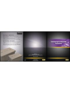
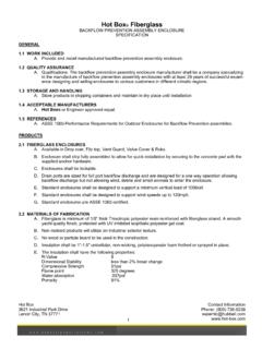
9 5V-BAR Conductor ACCESSORIESFOR 90, 110 OR 250 AMP SYSTEMSCATALOG lbsV-90 EPGfor 90 amp (.68 kg)V-110 EPGfor 110 amp (.91 kg)V-225 EPGfor 250 amp (.91 kg)CATALOG lbsV-TUsed to draw two Conductor sections together (all Systems ) ( kg)Connector ToolPick-Up Guide AssemblyCATALOG lbsV-TCMolded plastic caps in lieu of end caps at transfer points (interlocks) along the Conductor run (all Systems ).10 (.04 kg)Transfer CapsCATALOG lbsV-JC160 F (71 c) Orange (Standard)*.02 (.01 kg)V-JCHT280 F (137 C) Yellow for High Temp *.02 (.01 kg)V-JC-GGreen for Ground (.01 kg)* Insulating joint covers are field installed over each joint to guard against accidental contact. One joint cover is required with each Conductor Coverfor Inverted V-Bar SystemsCATALOG lbsV-90PF110 ampere (for 90 & 110 amp sys).33 (.15 kg)Power-Feed Assemblyfor Inverted V-Bar SystemsCATALOG lbsV-HSingle Non-Metallic Snap-in (all sys).11 (.05 kg)Hanger Assembliesfor Inverted V-Bar SystemsNon-metallic guide with 19 (.)
10 5m) Conductor bar, polycarbonate hangers and a transfer cap for guiding collector assemblies onto the Conductor system after traveling free air. CATALOG lbsV-90 IJfor 90 amp (.02 kg)V-110 IJfor 110 amp (.02 kg)Used to interrupt power and isolate an area of the system . End Capsfor Inverted V-Bar SystemsAnchor Hanger Assembliesfor Inverted V-Bar SystemsIsolation PieceCATALOG lbsV-HANon-Metallic Snap-in w/ Nylon Drive Rivet (all sys).12 (.05 kg)Anchor Hangers should be used on all Systems less than 30 (9m) in length, at all transfer points / interlocks and where the Conductor movement must be controlled or restricted. CATALOG lbsV-EC fits over exposed ends of Conductor (all sys).04 (.02 kg)68-BAR Conductor ACCESSORIESFOR 90, 110 OR 250 AMP SYSTEMSCATALOG lbs8-90 EPGfor 90 amp (.68 kg)8-110 EPGfor 110 amp (.91 kg)8-250 EPGfor 250 amp (.91 kg)CATALOG lbs8-TUsed to draw two Conductor sections together (all Systems ) ( kg)Connector ToolPick-Up Guide AssemblyCATALOG lbs8-TCMolded plastic caps in lieu of end caps at transfer points (interlocks) along the Conductor run (all Systems ).