Transcription of PRACTICAL DESIGN OF WATER DISTRIBUTION SYSTEMS
1 PDHonline Course C182 (4 PDH) PRACTICAL DESIGN of WaterDistribution Systems2012 Instructor: Jeffrey A. Gilbert, Online | PDH Center5272 Meadow Estates DriveFairfax, VA 22030-6658 Phone & Fax: Approved Continuing Education PDH Course C182 Page 1 of 28 PRACTICAL DESIGN of WATER DISTRIBUTION SYSTEMS Jeffrey A. Gilbert, Course Content INDEX Section Title Page MATERIALS 3 DEFINITIONS 3 DUCTILE IRON pipe 3 PLASTIC pressure pipe 6 PROTECTION 6 FITTINGS
2 7 VALVES 8 BOLTS, NUTS and GASKETS 8 DESIGN 8 WATER DEMAND 8 WATER DISTRIBUTION SYSTEMS 10 WATER DISTRIBUTION MODELING 11 PUMPS 13 VALVES 17 TANKS AND RESERVOIRS
3 18 CONTROLS DEVICES 19 EPA 20 LAYING OUT A PROJECT 21 EXISTING DATA 22 SCHEMATIC GENERALLY 22 pressure ZONES 23 COMPILED DATA 23 BUILDING THE MODEL 24 TROUBLESHOOTING A MODEL 26 FINAL NOTES 27 SUMMARY 27 RELATED
4 LINKS 28 PDH Course C182 Page 2 of 28 MATERIALS DEFINITIONS Ductile Iron pipe (DIP)- pipe which is manufactured from ferrous material in which a major portion contains carbon occurring as a free graphite in substantially nodular or spheroidal form. (Reference: ANSI/AWWA C110 ). ANSI-American National Standards Institute AWWA-American WATER Works Association Flanged Joint- A pipe joint that has a flared flange made into the pipe end to receive bolts to couple an adjoining flanged pipe or fitting.
5 Gray Iron pipe - pipe which is manufactured from ferrous material in which a major portion contains carbon occurring in the form of flakes interspersed throughout the metal. Mechanical Joints- Mechanical joints are pipe joints that are gasketed and bolted together. See ANSI/AWWA C111 Push on pipe Joints- Single rubber gasket pipe joints where the pipe sections are pushed together and not restrained. See ANSI/AWWA C111 DUCTILE IRON pipe ANSI/AWWA C110 DIP from 3 to 24 with mechanical joints or push-on joints is pressure rated for 350 psi. DIP with flanged joints is rated for 250 psi except that sizes 12 and smaller with special gaskets can be rated for 350 psi.
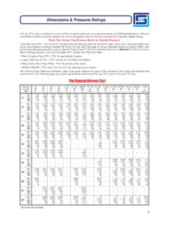
6 Gray iron fittings for this standard are rated at 150 psi or 250 psi for all joints. See Table below. DIP 30 to 64 pressure class 150 to 350 DIP Outside coatings to be petroleum asphaltic, 1 mil thick. This material adheres to raw DIP and does not become brittle in any condition, buried or exposed. PDH Course C182 Page 3 of 28 pressure Class 150 200 250 300 350 Size in. Outside Diameter in. Nominal Thickness in inches 4 - - - - 6 - - - - 8 - - - - 10.
7 12 - - - - 14 - - 16 - - 18 - - 20 - - 24 - 30 32 36 42
8 48 54 60 64 ANSI/AWWA C104 , DIP inside coatings are cement-mortar lined for use under normal conditions.
9 Sleeves plugs or caps generally are cement-mortar lined. Sleeves, plugs and caps may be specified with petroleum asphaltic coating, 1 mil thick. Under special conditions, other types of coatings are available. ANSI/AWWA C150/ This is the standard for DIP pipe thickness. AWWA C150 specifies the wall thickness for various working pressures. For example, an 8 pipe with a working pressure of 150 psi, requires a wall thickness of inches and requires the use of pressure Class 350. A working pressure of 150 psi for a 24 pipe requires a wall thickness of inches and the use of pressure Class 200 pipe . Table 13 of the ANSI/AWWA C150/ standard lists nominal pipe sizes from 3 to 64-inch for working pressures from 150 psi to 350 psi.
10 The table below provides the designer with ANSI/AWWA trench and cover criteria. Since some of these depths are generally impractical for most applications, rarely would a designer be concerned about depth of trench when using DIP. PDH Course C182 Page 4 of 28 Laying Conditions Maximum Depth of Cover in Feet(2) Size in. pressure Class Thickness in. Working pressure (1) psi Type 1 Type 2 Type 3 Type 4 Type 5 4 350 350 53 61 69 85 100(3) 6 350 350 26 31 37 47 65 8 350 350 16 20 25 34 50 10 350 350 11** 15 19 28 45 12 350 350 10** 15