Transcription of Preplumbed Sewage Pump System - Simer Pumps
1 Model 3963C. 293 Wright Street, Delavan, WI 53115. Phone: 1-800-468-7867. Fax: 1-800-390-5351. Web Site: Preplumbed Sewage Pump System installation , Operation, & Parts Manual Safety Information 7. Vent Sewage or septic tank according to local codes. Carefully read and follow all safety instructions in this manual 8. Do not install the basin or pump in any location classified or on pump. as hazardous by the United States National Electrical Code (NEC), or by the Canadian Electrical Code (CEC), indicates a hazard which, if not avoided, will where applicable.
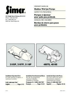
2 Result in death or serious injury. Pump Specifications indicates a hazard which, if not avoided, could Power Supply 115V. result in death or serious injury. Individual Branch Circuit Amps indicates a hazard which, if not avoided, could Maximum Liquid 130 F(55 C)*. result in minor or moderate injury. Discharge 2 NPT. NOTICE addresses practices not related to personal injury. 1. Read these rules and instructions carefully. Failure to Description The Simer Sewage Pump System , Model Number 3963C is follow them could cause serious bodily injury and/or ideal for basement installations, pumping below-grade toilets, property damage.
3 And laundry facilities. It includes a submersible Sewage pump, 2. Check your local codes before installing. You must comply a premium heavy duty structural foam, corrosion resistant with their rules. sump/ Sewage basin and lid, and a check valve for easy Hazardous voltage. Can shock, burn, or installation . kill. During operation the pump is in avoid fatal This submersible pump is designed for effluent and wastewater shocks, proceed as follows if pump needs servicing: removal, sump drainage, dewatering and flood control. 3A. Disconnect power to outlet box before unplugging pump.
4 The pump has built in thermal overload protection and 3B. Take extreme care when changing fuses. Do not stand in an automatic reset. The mechanical seal and ball bearings water or put your finger in the fuse socket. on the motor shaft are permanently lubricated. Stainless steel hardware and a heavy duty lift out ring allow for easy 3C. Do not modify the cord and plug. When using the cord disassembly after extended use. and plug, plug into a grounded outlet only. When wiring to a System control, connect the pump ground lead to the The basin is used for residential, commercial, and industrial System ground.
5 Collection of Sewage , effluent drainage and seepage water. The 4. Do not run the pump dry. Dry running can overheat the basin cover kit includes an inlet hub, a gas tight cover, cord pump, (causing burns to anyone handling it) and will void seals, gaskets, and hardware. No special tools or sealants are the warranty. required. 5. The pump normally runs hot. To avoid burns when NOTICE: This unit is not designed for applications involving salt servicing pump, allow it to cool for 20 minutes after shut- water or brine! Use with salt water or brine will void warranty.
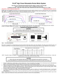
6 Down before handling it. 6. The pump is permanently lubricated. No oiling or greasing is required in normal operation. for overhaul, see instructions under Service . Pump, Motor, Switch, & Cord Specifications Individual Switch Setting in inches (mm) Discharge Model Motor Motor Full Branch Circuit Cord Length Adapter Number HP Load Amps Required (Amps) in ft. (m) On Off Size 3963 1/2 20 10 ( ) 16 (406) 7 (178) 2 . 2011 SIM538 (Rev. 4/20/11). Peformance installation 2. Performance circuit breakers according to the Motor, Switch and Cord Specifications chart.
7 GPM AT TOTAL FEET. Model 5 10 15 No flow Risk of electrical shock and fire. Be sure that at height power supply information (Voltage/ Hertz/Phase) on pump CAPACITY GALLONS/MINUTE shown below motor nameplate matches incoming power supply exactly. 3963C 122 90 45 18 Install pump according to all electrical codes that apply. *For performance at maximum temperature see Catalog. Explosion hazard. Improper ventilation of sewer gases can result in leakage of methane sewer gas, and a installation possible explosion of fumes, resulting in severe injury or death.
8 Hazardous voltage. Can shock, burn or kill. Do Vent basin according to all local codes. not lift pump by the power cord. See Cord Lift Warning on NOTICE: Proper ventilation is needed to prevent negative basin Page 3. pressure and to provide air for proper aerobic activity within NOTICE: Install the pump on a hard, level surface (cement, the basin. asphalt, or inside a sump basin, etc.). Never place the pump The Sewage basin should be located at the lowest place in the directly on earth, clay or gravel surfaces. basement or area to be drained.
9 Floor drains from other areas in the basement may be tiled into the basin. Drain tile around Piping a house foundation may also be tiled into the basin, effectively Piping must not be smaller than pump discharge. removing water and relieving pressure from this area. When installed in a Sewage System , the pipe must be capable of Basin covers are used to exclude refuse from the basin. handling semi-solids of at least 2 (51mm) in diameter. NOTICE: Read and understand this instruction manual before The rate of flow in the discharge pipe must keep any solids your concrete floor is poured.
10 Present in suspension in the fluid. To meet minimum flow requirements (2 feet per second in the discharge line), size the installation instructions . See Figure 1. pipe as follows: 1. Dig the hole for the Sewage basin and the sub-base. The hole must be deep enough so the finished floor is flush A Pipe Size Of: Will Handle a Flow Rate Of: with the top of the basin. Refer to Figure 1, Page 3. 1-1/2 (38mm) 12 GPM NOTICE: The sub-base should include 4 of sand or gravel. 2 (51mm) 21 GPM The maximum diameter of crushed rock should be 1/2.