Transcription of PRESSURE REDUCING CONTROL VALVE - Watts
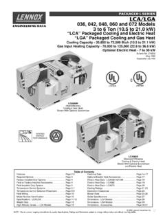
1 PRESSURE REDUCING . CONTROL VALVE . 06/08. F115 (Globe). Classic Series F1115 (Angle). Schematics Throttles to reduce high upstream PRESSURE to REDUCING setpoint is adjustable constant lower downstream PRESSURE 2. Standard Components P/L 1 Main VALVE (Single Chamber). 2 PRESSURE REDUCING CONTROL (AOS) 3 Fixed Orifice X. 3. Options & Accessories X X. X Isolation Cocks (2). Y/FC FC Flo-Clean Strainer (1). Y Y-Strainer (Replaces Flo-Clean) (2). 1 ACS Adjustable Closing Speed (3) (Replaces Fixed Orifice). AOS Adjustable Opening Speed (1). FLOW P Position Indicator (3). CLOSES VALVE . L Limit Switch (3). OPENS VALVE . (1) Standard 3 & Smaller (2) Standard 4 & Larger (3) Optional All Sizes Operations The Watts ACV PRESSURE REDUCING CONTROL VALVE is designed to automatically reduce a fluctuating higher upstream PRESSURE to a constant lower downstream PRESSURE regardless of varying flow rates.
2 It is con- trolled by a normally open, PRESSURE REDUCING pilot designed to: 1) Open (allowing fluid out of the main VALVE cover chamber) when downstream PRESSURE is below the adjustable setpoint, and 2) Close (allowing fluid to fill the main VALVE cover chamber) when downstream PRESSURE is above the adjustable setpoint. A decrease in downstream PRESSURE causes the VALVE to modulate toward an open position, raising downstream pres- sure. An increase in downstream PRESSURE causes the VALVE to modulate toward a closed position, lowering downstream PRESSURE . Installation Guidelines 8550 Hansen Road Houston, Texas 77075 (Ph) (Fx) F115 (Globe).
3 Classic Series F1115 (Angle). Materials Globe Angle Body & Cover: Ductile Iron ASTM A536 L. coating : NSF Listed Fusion D M. Bonded epoxy Lined and Coated Trim: 316 Stainless Steel (1-1/4 8 ) K. ASTM B62 Bronze (10 ). (Stainless Steel Optional) H I J. Elastomers: Buna-N (standard). EPDM (optional). Viton (optional) A E. B F. Stem, Nut & Stainless Steel C G. Spring: Operating PRESSURE Operating Temperature Pilot System Tubing & Fittings Threaded = 400 psi Buna-N: 160 F Maximum REDUCING CONTROL Copper / Brass (Standard). 150 Flanged = 250 psi EPDM: 300 F Maximum 20-175 psi (Standard) Stainless Steel (Optional). 300 Flanged = 400 psi Viton: 250 F Maximum 0-30 psi (Optional).
4 100-300 psi (Optional). Dimensions A B C D E F G H I J K L M. VALVE GLOBE GLOBE GLOBE COVER TO ANGLE ANGLE ANGLE ANGLE ANGLE ANGLE PORT PORT PORT SHIPPING. SIZE THRD. 150# 300# CENTER THRD. 150# 300# THRD. 150# 300# SIZE SIZE SIZE WEIGHTS*. 1-1/4 7-1/4 - - 3-1/2 3-1/4 - - 1-7/8 - - 1/4 1/2 1/8 15. 1-1/2 7-1/4 8-1/2 9 3-1/2 3-1/4 4 - 1-7/8 4 - 1/4 1/2 1/8 15. 2 9-3/8 9-3/8 10 4-15/16 4 4 4-1/4 4 4 4-1/4 1/2 1/2 1/4 35. 2-1/2 11 11 11-5/8 7 5-1/2 5-1/2 5-13/16 4 4 4-5/16 1/2 1/2 3/8 65. 3 10-1/2 12 13-1/4 7 5-1/4 5-3/4 6-1/8 5-1/4 5-3/4 6-1/8 1/2 1/2 3/8 95. 4 - 15 15-5/8 8-5/8 - 6-3/4 7-1/8 - 6-3/4 7-1/8 1/2 1/2 3/8 190.
5 6 - 20 21 11-3/4 - 8-1/2 8-7/8 - 8-1/2 8-7/8 1/2 1/2 1/2 320. 8 - 25-3/8 26-3/8 15-3/4 - 11 11-1/2 - 11 11-1/2 1/2 1 1/2 650. 10 - 29-3/4 31-1/8 18-3/4 - 14-7/8 15-5/8 - 14-7/8 15-5/8 1 1 1 940. For larger sizes consult factory VALVE Cover Chamber Capacity VALVE Size (in) 1-1/4 1-1/2 2 2-1/2 3 4 6 8 10. 4 4 4 10 10 22 70 - - Gal - - - - - - - 1-1/4 2-1/2. VALVE Travel VALVE Size (in) 1-1/4 1-1/2 2 2-1/2 3 4 6 8 10. Travel (in) 3/8 3/8 1/2 5/8 3/4 1 1-1/2 2 2-1/2. 8550 Hansen Road Houston, Texas 77075 (Ph) (Fx) F115 (Globe). Classic Series F1115 (Angle). Sizing Size (in) 1-1/4 1-1/2 2 2-1/2 3 4 6 8 10. Maximum Continuous (GPM) 95 130 210 300 485 800 1850 3100 5000.
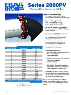
6 Maximum Intermittent (GPM) 119 161 265 390 590 1000 2300 4000 6250. Minimum Continuous (GPM) 1 1 1 20 30 50 115 200 300. Maximum continuous flow based on velocity of 20 ft. per second. Maximum intermittent flow based on velocity of 25 ft. per second. Minimum continuous flow based on velocity of 1 ft. per second. NOTE: The above chart is a suggested guide. Inlet PRESSURE , outlet PRESSURE , minumum, normal and maximum flow rates should be considered for specific VALVE sizing. Contact Watts ACV for details. Cavitation Chart CAVITATION CHART. After selecting the VALVE size, locate inlet and outlet pressures on this chart.
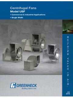
7 If the intersection point falls in the shaded area, cavitation can occur. Operation of valves continually in the cavitation zone should be avoided. Consult Watts ACV for alternatives. INLET PRESSURE - PSI CAVITATION ZONE. 300. 280. 260. 240. 220. 200. 180. 160. 140. 120. 100. 80. 60. 40. 20. 0 10 20 30 40 50 60 70 80 90 100 110 120 130 140. OUTLET PRESSURE - PSI. 8550 Hansen Road Houston, Texas 77075 (Ph) (Fx) F115 (Globe). Classic Series F1115 (Angle). Cross-Sectional Detail Main VALVE 1 10. 2 11. 3. 12. 4. 13. 5. 14. 6. 7 15. 8 16. 9 17. ITEM DESCRIPTION MATERIAL. 1 Cover ASTM A536 65-45-12 epoxy Coated Ductile Iron 2 Cover Bearing SAE 841 Bronze 3 Shaft / Stem ASTM A276 304 Stainless Steel 4 Stud ASTM A570 Zinc Plated Steel 5 Cover Nut ASTM A570 Zinc Plated Steel 6 Diaphragm* Buna-N (Nitrile).
8 7 Body ASTM A536 65-45-12 epoxy Coated Ductile Iron 8 Quad Seal* Buna-N (Nitrile). 9 Seat Ring ASTM A743 CF8M (316) Stainless Steel (8 and Smaller). ASTM B62 Bronze (10 and Larger). 10 Spring ASTM A276 302 Stainless Steel 11 Stem Nut ASTM A276 304 Stainless Steel 12 Diaphragm Washer ASTM A536 65-45-12 epoxy Coated Ductile Iron 13 Spacer ASTM A276 304 Stainless Steel 14 Quad Seal Retainer ASTM A536 65-45-12 epoxy Coated Ductile Iron 15 O-Ring* Buna-N (Nitrile). 16 Quad Seal Plate ASTM A743 CF8M (316) Stainless Steel (8 and Smaller). ASTM B62 Bronze (10 and Larger). 17 Seat Gasket* Buna-N (Nitrile). * Contained in Main VALVE Repair Kit 8550 Hansen Road Houston, Texas 77075 (Ph) (Fx) F115 (Globe).
9 Classic Series F1115 (Angle). Cross Sectional Detail Model 263AP. PRESSURE REDUCING Pilot 6. 1. 7. 2. 3. 4 8. 9. 5. 10. 11. Gauge Inlet Outlet 12. ITEM DESCRIPTION ITEM DESCRIPTION. NUMBER NUMBER. 1 Adjusting Screw 9 Stem Assembly*. 2 Jam Nut 10 Bucking Spring 3 Spring Housing 11 O-Ring*. 4 Cap Screw 12 Bottom Cap 5 Body 6 Spring Guide *Included in Repair Kit 7 Spring 8 Diaphragm Assembly*. 8550 Hansen Road Houston, Texas 77075 (Ph) (Fx) F115 (Globe). Classic Series F1115 (Angle). Installations Prior to installation, flush line to remove debris. Install VALVE horizontally in line (cover facing up), so flow arrow matches flow through the line.
10 Avoid installing valves 6 and larger vertically. Consult factory prior to ordering if installation is other than described. Install inlet and outlet isolation valves. NOTE: When using butterfly valves, insure disc does not contact CONTROL VALVE . Damage or improper VALVE seating may occur. Provide adequate clearance for VALVE servicing and maintenance. Install PRESSURE gauges to monitor VALVE inlet and outlet PRESSURE . If installation is subjected to very low flow or potentially static conditions, it is recommended a PRESSURE relief VALVE (1/2 minimum) be installed downstream of the PRESSURE REDUCING VALVE for additional system protection.