Transcription of Pressure Test Procedures - Stanford University
1 ENVIRONMENT, SAFETY & HEALTH DIVISION. Chapter 14: Pressure Systems Pressure Test Procedures Product ID: 613 | Revision ID: 1790 | Date published: 9 December 2015 | Date effective: 9 December 2015. URL: 1 Purpose The purpose of these Procedures is to ensure that Pressure tests are conducted safely and effectively. They cover Pressure testing of new and existing Pressure systems or components at a test Pressure more than 0 psig. They apply to mechanics, supervisors, inspectors, custodians, and subcontractors responsible for Pressure tests . 2 Procedures Pressure tests are performed to ensure the safety, reliability, and leak tightness of Pressure systems. A. Pressure test is required for a new Pressure system before use or an existing Pressure system after repair or alteration. There are two methods for Pressure tests : hydrostatic and pneumatic. A hydrostatic test is performed by using water as the test medium, whereas a pneumatic test uses air, nitrogen, or any non-flammable and non- toxic gas.
2 At SLAC Pressure tests must be hydrostatic unless pneumatic tests can be justified. Pressure tests must always be performed under controlled conditions, following an approved test plan, and documented in a test record. A single approved test plan may be used for several similar tests , but a separate test record is required for each. Hydrostatic Test Procedure Hydrostatic is the preferred method of Pressure test at SLAC. Step Person Action Planning 1. Mechanic Obtains test Pressure after consulting the project engineer Note: when hydrostatic test is performed on an existing Pressure system , the original hydrostatic test Pressure must not be exceeded. 2. Mechanic Completes Pressure test plan and submits for approval 3. Supervisor Approves plan 4. Pressure systems Approves plan (not required for routine testing of existing systems). program manager 9 December 2015 SLAC-I-730-0A21C-033-R004 1 of 7.
3 SLAC National Accelerator Laboratory Environment, Safety & Health Division Chapter 14 | Pressure Test Procedures Step Person Action Performing 5. Mechanic Ensures the Pressure gauges used have current calibration stickers 6. Mechanic Removes all persons not directly involved with the test from the immediate test area 7. Mechanic Removes Pressure relief valves or non-reclosing relief device from the vessel or test boundary where the test Pressure will exceed the set Pressure of the valve OR. Holds down each valve by means of an appropriate test clamp and pressurizes both sides of non-reclosing relief devices Installs temporary, higher-rated devices where practical 8. Mechanic Installs the calibrated test gauge so it is visible at all times 9. Mechanic Ensures the skillet blanks or test plugs or clamps are appropriate for use and are free of obvious defects 10. Mechanic Fills and vents system as necessary to remove as much air as practical 11.
4 Mechanic Ensures that water used for the test is at not less than ambient temperature, but in no case less than 70 F. 12. Mechanic Pressurizes the system , raising the Pressure in the system gradually until the designated test Pressure is achieved 13. Mechanic Maintains this test Pressure for 10 minutes before inspection. Then, if test is above maximum allowable working Pressure (MAWP), reduces to MAWP while making a full thorough inspection for leaks. 14. Mechanic Ensures the metal temperature at the time of the hydrostatic test does not exceed 120 F. 15. Mechanic If there is evidence of structural distortion, either rejects the system or repairs as advised by the inspector 16. Mechanic If there is leakage in the system , performs the following as appropriate: Ensure repairs is performed and returns to Step 12 or Rejects the system 17. Mechanic When the test is completed, vents the test Pressure to atmosphere and returns relief devices to normal configuration Recording 18.
5 Inspector Signs Pressure test record 19. Mechanic Completes Pressure test record and submits copy to the Pressure systems program manager 20. Mechanic Submits copies of the test plan and test record to the custodian 9 December 2015 SLAC-I-730-0A21C-033-R004 2 of 7. SLAC National Accelerator Laboratory Environment, Safety & Health Division Chapter 14 | Pressure Test Procedures Pneumatic Test Procedure Pneumatic tests are potentially more dangerous than hydrostatic because of the higher level of potential energy. Pneumatic tests may be performed only when at least one of the following conditions exists: When Pressure systems are so designed that they cannot be filled with water. When Pressure systems are to be used in services where traces of the testing medium cannot be tolerated. Using a pneumatic test instead of hydrostatic requires approval by the Pressure systems program manager.
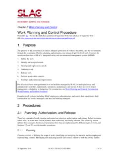
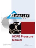
6 In addition to a justification, a piping schematic for pneumatic Pressure test is required. A recommended typical piping schematic for pneumatic test is shown in Figure 1. Important Installation of a Pressure relief valve is required for a pneumatic test. Figure 1 Recommended Typical Piping Schematic for Pneumatic Testing 9 December 2015 SLAC-I-730-0A21C-033-R004 3 of 7. SLAC National Accelerator Laboratory Environment, Safety & Health Division Chapter 14 | Pressure Test Procedures Step Person Action Planning 1. Mechanic Obtains test Pressure after consulting the project engineer Note: ensures that the pneumatic test Pressure does not exceed the established test Pressure of the system , unless otherwise specified in the design documents. 2. Mechanic Completes Pressure test plan, including justification for pneumatic testing and a piping schematic for the test, and submits for approval 3.
7 Supervisor Approves plan 4. Pressure systems Approves plan program manager Performing 5. Mechanic Ensures that the test gauge has a current calibration sticker. (A Pressure relief valve or non-reclosing relief device may be installed in the test medium supply line to ensure that this limit is not exceeded.). 6. Mechanic Ensures that the test area is properly flagged, barricaded, or otherwise controlled to prevent unauthorized personnel entry 7. Mechanic Removes from the immediate area all persons not directly involved in the test 8. Mechanic Installs the calibrated test gauge so it is visible at all times 9. Mechanic Verifies that the Pressure is continually monitored to ensure that Pressure never exceeds the designated test Pressure of the system 10. Mechanic Removes relief devices from the system to be tested, where the test Pressure will exceed the set Pressure of the device OR.
8 Holds down each valve disk by an appropriate test clamp and equalizes Pressure on non-reclosing relief devices 11. Mechanic Pressurizes the system , raising Pressure in the system gradually until not more than 1/2 of the test Pressure is achieved 12. Mechanic Increases the Pressure slowly in steps of approximately 1/10 of the test Pressure until the required test Pressure has been reached 13. Mechanic Reduces the Pressure to the maximum operating Pressure before proceeding with the inspection; holds the Pressure for a sufficient period of time to permit inspection of the system 14. Mechanic Checks the Pressure gauge periodically for indications of leakage 15. Mechanic Applies a soap solution to accessible welds, screwed pipe joints, flanges, et cetera where leakage is suspected 16. Mechanic If there is evidence of structural distortion, either rejects the system or repairs as advised by the inspector 17.
9 Mechanic If there is leakage in the system , performs the following as appropriate: Ensures repair is performed and return to Step 11 or 9 December 2015 SLAC-I-730-0A21C-033-R004 4 of 7. SLAC National Accelerator Laboratory Environment, Safety & Health Division Chapter 14 | Pressure Test Procedures Step Person Action Rejects the system 18. Mechanic When the test is completed, vents the test medium to approved discharge vicinity/atmosphere Recording 19. Inspector Signs Pressure test record 20. Mechanic Completes Pressure test record and submits copy to the Pressure systems program manager 21. Mechanic Submits copies of the test plan and test record to the custodian Test Pressure There are many types of Pressure systems designed under American Society of Mechanical Engineers (ASME) code, and repaired under the National Board Inspection Code (NBIC). The test Pressure of various Pressure systems must be calculated based on following.
10 Table 1 Test Pressures for New Pressure Vessel and Piping Systems system Code Hydrostatic Pneumatic Boiler power ASME Section I MAWP Not permitted Boiler heating ASME Section IV MAWP Not permitted Pressure vessel ASME Section VIII. Division 1 MAWP MAWP. Division 2 MAWP MAWP. Power piping ASME Section design Pressure design Pressure Process piping ASME Section design Pressure design Pressure Building services piping ASME Section design Pressure design Pressure Sprinkler system NFPA 13 200 psi 40 psi 9 December 2015 SLAC-I-730-0A21C-033-R004 5 of 7. SLAC National Accelerator Laboratory Environment, Safety & Health Division Chapter 14 | Pressure Test Procedures Table 2 Test Pressures for Existing Pressure Vessel and Piping Systems Type of Work Code Hydrostatic Pneumatic Inspection NBIC SV setting Agreement between owner and inspector Alteration NBIC MAWP According to original code of construction Repair NBIC MAWP Minimum Pressure required verifying leak tightness Notes: NBIC: National Board Inspection Code MAWP: maximum allowable working Pressure SV: safety valve 3 Forms The following forms are required by this procedure: Pressure Systems: Pressure Test Plan Form (SLAC-I-730-0A21J-044).