Transcription of Pressure Vessel Design for Engineering Plastics
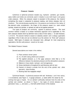
1 By Peter A. TuschakEngineering Plastics have been used forpressure Vessel applications for a longtime. Lighter bodies, ballcock valves, andspray paint containers (Figure 1) are just afew examples of successful developmentsin this advances in resin developmentare now creating still further of increasing stiffness and tough-ness have been commercialized. Newamorphous Plastics , suitable for blowmolding sizable parts, have also beendeveloped, opening the way to one stepmanufacturing of these products. Theabove activity creates new opportunitiesfor Pressure vessels in Engineering article describes the results of studiesmade by DuPont on stress distributions inplastic Pressure vessels and of the codesand standards that regulate their designers use nominal hoop stressformulas as a basis for Vessel Design .
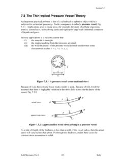
2 We studied atypical Pressure Vessel , Figure 2, usingfinite element stress analysis on a digitalcomputer and found that, due to geometri-cal discontinuities, stresses as high as threeto six times the nominal hoop stress canoccur. The results of a typical case areshown in Figure 3. The section where thecylindrical Vessel and the torisphericalhead join is magnified, and lines of con-stant stress (stress contours) through thesection are shown. The maximum stress isapproximately six times the nominal hoopstress and it occurs on the inside surface ofthe knuckle STRESS MAY NOTBE ALL YOU NEED TOKNOW FINITE ELEMENTANALYSIS DEMONSTRATESIMPORTANCE OF THE TYPE OFEND CLOSURE SPECIFIEDS = PR/t for thin walled vessels, orS = P xfor thick walled vesselsR+2oR2iR 2oR2iFigure vesselssuch as these have long beenproduced in Engineering Plastics .
3 Stiffer and tougherresins now open up evenmore opportunities for larger,more critical Vessel Design forEngineering Plastics2 Generous Safety Factors RequiredSome of the industrial codes and standardsthat regulate Pressure Vessel Design recog-nize the existence of stress concentrationsand require the use of generous safety fac-tors. The American Society of MechanicalEngineers, as an example, recommendsthat operating Pressure in plastic vessels beno more than one sixth of the burst pres-sure, as determined by hydrostatic Technical Services Laboratory (TSL) Design group established certain guidelinesfor Pressure Vessel Design based in part onthe ASME and other industrial a Pressure Vessel with require-ments as follows.
4 The internal diameter ofthe Vessel to be 102 mm (4 0 in), the over-all length not to exceed 254 mm (10 in),with the cylindrical portion to be at least203 mm (8 in) long, as in Figure 4. Thematerial must be FDA approved. The oper-ating Pressure will be 276 kPa (40 psi),intermittently applied, with burst pressureat least 2068 kPa (300 psi). The operatingtemperature to be 23 C (73 F) at 50 per-cent relative humidity (RH). The first stepin the Design procedure is to determine atentative wall thickness: Using the nominalhoop stress formula we can writeBased on our finite element study and oth-er relevant information, we can assumethat the maximum stress will bewhere K is the stress concentration magnitude of K depends on the type ofend closure we select.
5 We saw in our finiteelement example that for a torisphericalhead, K = 6. Hemispherical and semiellip-soidal heads produce lower stress concen-tration factors. Since the dimensionalrequirements preclude a hemisphericalclosure it would allow only a 152 mm (6in) straight section we ll select a 2:1semi-ellipsoidal head. With this choice thestress concentration factor becomes four toone, Now, Because of the need for an FDA approvedmaterial we ll choose Delrin 500 acetalresin, for which at 23 C (73 F). Thus, with a wall thickness of mm ( in),the predicted burst Pressure is 2068 kPa(300 psi) as required.
6 Using the ASME guidelines adopted by TSL, we will nowpostulate the operating Pressure to be lessthan one sixth of the burst Pressure , the required operating Pressure is276 kPa (40 psi), the Design meets therequirements. The maximum stress at theoperating Pressure becomes and the safety factor is nowThe above data were obtained by analysisonly. The next, and perhaps most importantstep in the Design is to mold a prototypevessel. Analysis does not take into accountSH=P RtSmax= KSHF igure section of Pressure Vessel analyzed using the ansys finite element distribution knuckle section oftypical Pressure Vessel SH= nominal hoop stressFigure of sample pressurevessel of Delrin 500 Smax= 4 x SHSmax= 68948 kPa (10,000 psi)t = 4 x P xRSmaxt =4 x2068 = mm, or68948t =4 x300 x2 = ,000 Pop PBURST= 345 kPa (50 psi)6S(max.)
7 Op)= PR xK = 276 x x 4 = 9191 kPa, x 2 x 4 = 1333 =S(max)S(max op)=689489191=10,0001333= lines, gate size, effect of gate loca-tions, etc.; thus, actual testing must be per-formed to establish the burst Pressure . Inthe present case, since the Vessel must sur-vive a large number of cycles, it will under-go fatigue testing first. This consists ofcycling the Pressure from zero to 276 kPa(40 psi), 100,000 times at 23 C (73 F) and50 percent cycling test will be followed by thehydrostatic burst test. The same specimenthat was cycle tested will be burst.
8 If theburst Pressure is equal to or greater than2068 kPa (300 psi), our job is finished. Onthe other hand, if the burst Pressure is lessthan 2068 kPa, we must modify the Design ,or lower the required operating Pressure . Ifa Design modification is made, a new pro-totype will be tested to make sure thedesired performance is achieved. There-fore, Pressure Vessel Design is an iterativeprocedure and the designer should remem-ber that final testing of the product is theultimate proof of this article presents a rationalapproach to Pressure Vessel Design withengineering Plastics , it has not been possi-ble to cover all aspects of Vessel example, long term pressurizationmight require considerations of materialcreep in determining maximum allowablestress.
9 Also, the question of Pressure reliefdevices was not addressed. These, and oth-er considerations are continually understudy by the TSL Design group and thelessons learned are available for applica-tion to customer problems on a Tuschak is a member of thedesign group at Chestnut Run sTechnical Services Laboratory. Thisarticle was originally published inthe Winter 1984 issue of Engi-neering Design