Transcription of Printing and Assembly Challenges for Quad Flat …
1 Printing AND Assembly Challenges FOR quad flat NO-LEAD (QFN) PACKAGES With proper stencil design, stencil technology selection, and PCB solder mask layout the Challenges that QFNs present to the Assembly process can be overcome. By William E. Coleman , Vic e President Tec hnology 1 | P a g e Colorado Springs, CO 80919 Phone: (719) 599-4305 Fax: (719) 599-4334 Printing and Assembly Challenges for quad flat No-Lead (QFN) Packages By William E. Coleman , Photo Stencil, Vice President Technology Benefits and Challenges QFN ( quad flatpack, no leads) and DFN (dual flatpack, no lead) are becoming more popular in new component releases.
2 Their very small form factor allows smaller packages, better grounding, and better heat sink thermal properties compared to other SMT packages. Most QFNs have a metal pad on the underside of the part for grounding and heat conduction. DFNs have a similar center metal pad but have leads on only two sides. Typical thickness of the QFN devices is .85mm and the body range from 3mm up to 12mm, so the packages are very small and very light. The QFN leads and ground plane conductor are flat and in the same plane on the bottom of the package. Printing solder paste 1-1 with the ground plane can cause the QFN to float during reflow, thus miss-registering the leads on the QFN and the pads on the PCB.
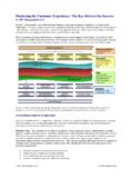
3 QFN float can be controlled by reducing the amount of solder paste printed on the ground plane. Typically a 50 to 60% reduction will solve the QFN float problem. However the aperture reduction must be done judicially. A Window Pane aperture is recommended for most cases. This allows the solder paste volatiles to easily escape during reflow without moving the QFN device. Figure 1 shows the benefits of window pane apertures for the ground plane. Figure 1. Benefit of Window Pane Ground Plane Apertures The next challenge is the actual aperture size in the stencil.
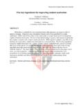
4 Figure 2 shows a 3mm QFN and a 4mm QFN device. Typical aperture widths as low as .175mm and aperture lengths as low as .4mm present a challenge to the Printing process as far as percent paste transfer. The other challenge is the solder mask employed on the PCB. 2 | P a g e Colorado Springs, CO 80919 Phone: (719) 599-4305 Fax: (719) 599-4334 PackagePitchI/OPackage Lead WidthPackage Lead LengthPCBPCBA perture NSMDA perture NSMDS tencil ThicknessArea Lead WidthPackage Lead LengthPCBPCBA perture SMDA perture SMDS tencil ThicknessArea Lead WidthPackage Lead LengthPCBPCBA perture SMDA perture SMDS tencil ThicknessArea Design for Typical QFN Apertures (NSMD)Stencil Design for Typical QFN Apertures (SMD)Stencil Design for Typical QFN Apertures (NSMD window)Table 1.
5 QFN, PCB, Stencil Design GuidelinesThere are three types of solder mask designs which are shown in Figure 3: a) SMD where the pad opening on the board is defined by the solder mask, b) NSMD where the pad itself defines the boundary of the pad and the solder mask is pulled back off the pad (typically .05 to .075mm per side), and c) NSMD Window. In the last case there is no solder mask between pads so bridging between pads is more likely than with solder mask between pads. Figure 3. Solder Mask Designs Stencil and PCB Design Considerations Table 1 shows stencil design guidelines for the three solder mask cases.
6 This table shows the package size, the lead pitch, the number of I/O, the package lead dimensions, the recommended PCB pad dimensions, the recommended stencil aperture dimension, recommended stencil thickness, and resulting Area Ratio. For NSMD the stencil aperture is 1-1 with the PCB pad dimension. It should be noted that the recommended length of the pad on the PCB compared to the length of the lead on the QFN is .2mm larger. As seen the Area Ratio for a .125mm thick stencil is >.66 for all the examples listed. Aperture size for the SMD is .05mm smaller than the PCB pad.
7 There are typically two reasons for this reduction. If the stencil is slightly misaligned to the PCB, paste could be printed on the solder mask. Also there might be high stress points if solder contacts the mask. The reduction in aperture size has reduced the Area Ratio making paste transfer more difficult. For Area Ratios below .66 Electroform stencils or Nano-Coated stencils are normally recommended. The final example in Table 1 is the NSMD Window. The pitch is .4mm leaving little room to put solder mask between pads on the PCB. Aperture size is also small giving a challenging Area Ratio for.
8 125mm thick stencils; therefore .100mm thick stencils are normally recommended to provide a more robust stencil Printing process window. 3 | P a g e Colorado Springs, CO 80919 Phone: (719) 599-4305 Fax: (719) 599-4334 Another problem arises when using a NSMD window when the solder mask is higher than the pad on the PCB. In this case the solder paste is extruded through the stencil since the stencil is not in contact with the PCB pads during Printing . This extruded paste will make contact with the bottom side of the stencil causing potential bridging during successive prints since there is no solder mask between neighboring pads.
9 Stencil wiping after every print may help reduce this problem. An Example of a NSMD Window PCB with solder mask above the height of the PCB pads is shown in Figure 4. Figure 4. NSMD-Window with Mask to pad gap of .03mm One possible solution suggested by a customer1 is a PCB side step stencil as shown in Figure 5. This is an Electroform stencil which is .08mm thick everywhere except in the QFN area inside the solder mask where it is .01mm thick. In this case the mask opening was of the order of .125mm per side except on the ends of the pad rows where it was less.
10 There are several limitations to this approach. Namely the spacing between the step and the solder mask is extremely small allowing for little miss-registration. Also the stencil is thinner for all other components except the QFNs which may yield insufficient paste. The first limitation could be addressed at the PCB design level by making the mask to pad clearance much larger; of the order of .25mm per side as well as leaving the ground plane without any solder mask surrounding. Figure 5. Step Electroform Stencil on PCB side - .1mm thick around QFN apertures and.