Transcription of Pro/DESKTOP® Tutorial Introductory Level – CAM
1 Pro/DESKTOP Tutorial Introductory Level CAM CAM 2 Written by Tim Brotherhood Copyright 2003, Parametric Technology Corporation (PTC) -- All rights reserved under copyright laws of the United States and other countries. PTC, the PTC Logo, The Product Development Company, Create Collaborate Control, Simple Powerful Connected, Pro/ENGINEER, Pro/DESKTOP, Wildfire, Windchill, and all PTC product names and logos are trademarks or registered trademarks of PTC and/or its subsidiaries in the United States and in other countries. All other product names and marks referenced herein are trademarks or registered trademarks of their respective holders.
2 Conditions of use Copying and use of these materials is authorized only in the schools of teachers who attend official training with a PTC certified trainer. All other use is prohibited unless written permission is obtained from the copyright holder. Acknowledgements John Hutchinson The College of New Jersey Fred Fogle The College of New Jersey Feedback In order to ensure these materials are of the highest quality, users are asked to report errors to PTC at Suggestions for improvements and other activities are also welcomed. CAM 3 TABLE OF CONTENTS CAM IN Removing 3 Axis 2 D vs Applications of 2 3D MODIFYING DESIGNS FOR Designing for Quality vs CAM IN THE Work MULTIPLE OBJECT Long Machining FROM CAD TO EXPORTING AN STL POST Post Processing Importing a 3D Size of Model (scaling).
3 24 CALCULATE TOOL On Screen POST PROCESSORS IN Modela Mill CAM 4 INTRODUCTION Computer aided manufacture (CAM) in schools includes a range of techniques including printing, embroidery, vinyl cutting, machining of resistant materials, etc. All of these are based on graphical images, most in two dimensions (2D). This booklet concentrates on techniques for taking three dimensional (3D) designs from Pro/DESKTOP and machining them out of resistant materials. In order to place this work in context, reference will be made where appropriate to 2D techniques. Designing is an important aspect of design and technology but equally vital is the capacity to manufacture.
4 Computer Aided Manufacture (CAM) is the logical extension of CAD but requires expensive machines. The software that controls CAM machines usually comes as part of the package but link software is required to convert Pro/DESKTOP files into machine instructions. CAM IN INDUSTRY Stereo Lithography Stereo Lithography is a term coined to describe a laser process for solidifying resin to form complex 3D components. It creates durable, highly accurate models but can take days to create large, detailed objects. The file format for rapid prototype models is known as STL and breaks the surface of an object into thousands of triangles.
5 Stereo Lithography machines are still the realms of large companies, often costing well over 100,000 each. The STL file format however is now being used to transfer files to machining equipment. CAM 5 LOM Laminated object manufacture (LOM) is a well-established industrial process that slices a component into wafer thin slices. These are cut from sheet material, usually paper or card, and bonded together to form a copy of the computer model. Models formed by this process are robust with properties similar to softwood or medium density fiberboard. A school version of this process is now available. Boxford a UK based machine tool manufacturer has produced RapidPro software.
6 This operates like a software wizard guiding the user through a series of screens. The slices are cut into sheets of self-adhesive cardboard or paper. A clever technique of guide pegs is used to align the slices when, with a bit of patience, they are glued together re-assemble the model. Fuse Deposition Modelling (FDM) This process is used extensively and produces dense, robust models that can be handled without fear of damage. Some plastics used in this process can be sterilized and used to prototype food products. FDM machines build models from very fine strands of thermoplastic. The technique could be likened to using a hot glue gun to build up layers of plastic onto a surface, gradually creating a component.
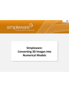
7 Because models are built in air the software adds scaffolding to support overhangs. CAM 6 Required model FDM model with scaffolding Models created using this technique are robust enough to be used for testing purposes. Automobile companies routinely produce FDM models of air ducts and manifolds to check flow characteristics. 3D Printers These machines use a technique where fine powder is laid down in layers with adhesive bonding the particles for each slice . Materials include cornstarch and plaster. Early examples of these machines cost up to $250,000 but the price is now below $50,000. Predictions suggest a machine will be available below $5,000 within 5 years, a point where schools may find them affordable.
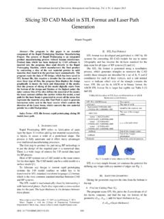
8 Pottery manufacturers make extensive use of this process to create prototypes and molds directly in plaster. The Hot House , a design center near Stoke on Trent, England offers a range of CAD and CAM services to the ceramic industries including 3D printing. CAM 7 Removing Material Spark erosion This technique is used to shape materials that are difficult to cut by mechanical methods. Titanium is one such material. A thin wire acts as the anode and the titanium blank is the cathode. A high voltage supply is connected between the electrodes and an electrolyte liquid sprayed over the work piece.
9 The cutting wire is gradually moved to create the required shape. For internal holes, like the one above in a suspension upright, the wire can be threaded through a pilot hole prior to starting the cut. Machining Machining components manually is a complex process even for experienced operators. Defining the instructions for a computer-controlled machine can also be very difficult. Programming tool paths and machine instructions is a highly specialized job, needing well-qualified engineers with high- Level ICT skills. CAM 8 Computerized milling machines are often described as Computer Numerically Controlled (CNC).
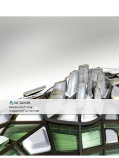
10 Machines need a set of instructions to determine the movement and speed of cutters and positioning motors. Picture courtesy of: The Manufacturing Engineering Centre University of Wales. 3 Axis Machining To explain CNC machining this diagram shows the worktable and cutting head. This shows the three axes of movement. The movement of each axis can be controlled independently. 2 D vs 3D Early CNC machining in schools was confined to 2D cutting due to the complexity of converting 3D co-ordinates into machine instructions. These instructions consist of a standardized language of G-Codes . Simplified, a straight cut would be programmed as a start point, end point and depth of cut.