Transcription of Pro/SHEETMETAL - Gary Lamit
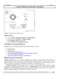
1 1 Pro/SHEETMETAL Figure Bracket and Bracket Detail Drawing OBJECTIVES Model sheet metal parts and create sheet metal drawings Create walls, reliefs, and bends Understand and create Bend Order Tables Produce Flat Pattern Instances of sheet metal parts Create form features and rips Produce sheetmetal drawings Pro/SHEETMETAL This Lesson introduces how to create and work with thin-walled parts using Pro/SHEETMETAL (Fig. ). Pro/SHEETMETAL parts are similar to Pro/E parts (even though their database is actually a bit different). Pro/SHEETMETAL parts are a Sub-type of parts. When you create a New file, if Part is the selected Type, you can choose sheetmetal as the Sub-type. From the New File Options dialog box you then choose the Template (Fig. ). sheet metal parts can also be used in assemblies, along with other Pro/E and/or Pro/SHEETMETAL parts. In addition, sheet metal parts can contain normal Pro/E features, such as solid protrusions, surfaces, and datum entities.
2 Figure Sub-type sheetmetal and Template options. 2 Using Pro/SHEETMETAL , you can create parts in either their formed (bent) shape (Fig. ) or the flattened shape. Once created, these parts can then be formed or flattened, as required. You can also use Family Tables to maintain the part in both states. Figure COAch for Pro/E, Pro/SHEETMETAL , Basic Concepts, Overview If you have COAch for Pro/E on your system, go to sheet metal design and complete the lessons. As sheet metal parts are flattened (or formed if you start with a flat state), Pro/SHEETMETAL utilizes a "Y factor" to allow for the fact that metal is elastic and stretches as it bends. Pro/SHEETMETAL will subtract from the actual length of the material to compensate for the elasticity. You can substitute a Bend Table for the Y factor if you so desire. Several default bend tables are provided with Pro/SHEETMETAL ; they are based on the tables from the Machinery Handbook.
3 The Pro/E part database is different when you create parts using Pro/SHEETMETAL . All sheet metal parts are by definition thin-walled constant-thickness parts. Because of this, sheet metal parts have some unique properties, that other Pro/E parts do no have. You may convert a solid part into a sheet metal part, but not a sheet metal part into a solid part. The solid must be a constant thickness. All sheet metal parts are constructed of features known as Walls. A sheet metal Wall feature is analogous to a Solid Protrusion. When you create Wall features, Pro/E is actually doing a great deal of work behind the scenes--it creates many internal datum planes and automatic alignment points that never appear on the screen. Another important sheet metal feature is a Bend. Bends are often generated automatically during the creation of Wall features. sheet metal drawings usually contain views both of the fully formed part and of the flat pattern, as in Figure You can place views of the part in both states on the same drawing by creating a multi-model drawing.
4 Figure COAch for Pro/ENGINEER, Pro/SHEETMETAL , Drawings, Flat State 3 There are many similarities between creating solid features in Pro/E and in Pro/SHEETMETAL . However, Pro/SHEETMETAL offers some additional special features. To create a sheet metal part in Pro/E, choose sheetmetal instead of selecting Solid from the New (file) dialog. The FEAT CLASS menu structure appears differently in Pro/SHEETMETAL mode. The first feature in any sheet metal part must always be a Wall feature, which is analogous to a Solid protrusion. After constructing the first Wall feature, you may create surface or solid features, as well as datum or sheet metal features. The OPTIONS menu is used only when constructing the first Wall feature. Subsequent sheet metal features are created from a different menu. Most of these options should look familiar; their functionality is identical to their Solid feature creation counterparts. There are two new options available when creating the first Wall feature in sheet metal mode: Flat and Offset.
5 The Offset option creates a wall that is offset from an existing surface. This is most useful for creating feature geometry in Assembly mode. With the Flat option, you can sketch the outline of a planar surface (Fig. ). Figure Sketch of First Wall and Modeled Wall sheet metal design Using Pro/SHEETMETAL In general, it is most effective to create sheet metal designs in their bent state and then unbend them for flat pattern geometry. Create your design as per your design intent. It is not necessary to create the design in the order of manufacture. sheet metal parts can be created in the Part mode or the Assembly mode. You can use the top-down approach to design when you use the Assembly mode. Typical sheet metal structures that can be designed with Pro/SHEETMETAL are cabinets and supporting structures for electrical and mechanical equipment (Fig. ). In these instances, you should design the cabinet and supporting structures around the internal components.
6 As with regular Pro/E parts created in Assembly mode, a sheet metal part can be dimensioned to the component parts that it is supporting. Figure Electronic Chassis 4 Before starting to create sheet metal features, remember to design the part in the as designed condition, , not as a flat pattern, unless you know all flat pattern details and dimensions. (Problems can arise when you modify a part that was designed as a flat pattern). Add as many bends to the part as possible before adding other features. Creating cuts at an angle or through bend areas might require larger dimensions for proper clearance. The proper feature creation order (Fig. ) and sketch references are essential. Figure Order of Feature Creation and References for Feature Creation Walls If you choose to create a sheet metal part in sheet metal mode, the first feature (other than datums) must be a wall.
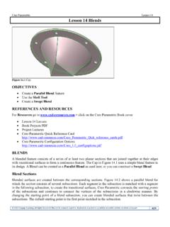
7 There are two types of walls: Base and Secondary. Pro/E grays out all the other feature types in the sheet metal menu until you have created the first (base) wall. There are several options for creating the base wall that are not available when you are adding (secondary) walls to the part. The feature forms available for the base wall include: Extrude Sketch the side section of the wall and extrude it a specified depth (Fig. ). Figure Base Feature, Extruded Wall Revolve Sketch the side section of the wall and revolve about an axis (Fig. ). Figure Base Feature, Revolved Base 5 Blend Create a sheet metal wall by blending several sections sketched in parallel planes as shown in Figure Figure Base Feature, Blended Wall Flat Sketch the boundaries of the wall (Fig. ). Figure Feature, Flat Wall Offset Create a wall that is offset from a surface (Fig. ). Figure Base Feature, Offset Wall Advanced Create a sheet metal wall-using datum curves, multiple trajectories.
8 Because you are in sheet metal mode, any features that you created through this menu are thin ones. Viewing a sheet metal Part When manipulating thin-walled models (like sheet metal or die-cast parts) it is often difficult to select the thin side surfaces when you wish to orient the view. Because of the thinness of a sheet metal part, using edges for orienting the part is more convenient than using the side surfaces. To orient the part: Choose a view command (Front, for example); then select a surface (wall). Select the corresponding view command (Top, for example) and select an edge of a wall. 6 Secondary Walls You can add flat walls, extruded walls, swept walls, extends, twists, and merged walls. They are attached to the edges on the part. Except for the Extends, these walls can be attached either to a whole edge or to a portion of it (partial walls, Sweeps, and Twists). Extends extrude a wall along the full length of the specified edge.
9 You can also add unattached walls, independent of the base wall, by checking Unattached in the Wall menu. The choice of walls to add to the base wall will depend on your design intent. Flat Walls and extruded walls must be attached to planar surfaces. Their attachment edges must be straight lines. Flat walls can have a section of any shape, but their profile is always flat. Extruded, walls can be sketched with a more complex profile. Extruded walls are always created as rectangular because they are extruded to a uniform depth; however, you can afterwards add Cut features to modify the wall shape. Swept walls can be attached to virtually any surface. Their attachment edge need only be a tangent chain. The three major geometry types for additional walls are Flat, Extruded and Swept (Partial walls are a subset of Extruded walls). With two additional menu options, No Radius and Use Radius, possible wall features are as follows: Flat Wall, No Radius Sketch the boundaries of the wall attached to the selected edge.
10 The adjacent wall must be either planar or a twist. The attachment edge must be a straight line. The new wall is automatically created coplanar with the adjacent planar wall or tangential with the end of the twist (Fig. ). Figure Flat Wall-No Radius Extruded or Partial wall, No Radius Sketch the side section of the wall that will be extruded along the attachment edge. You determine whether a bend is to be created when you are sketching the section. For a partial wall, the adjacent wall must be planar. For an extruded wall, the adjacent wall must be either planar or a twist. In all cases, the attachment edge must be a straight line. (Fig. ). Figure Extruded or Partial Wall-No Radius Swept Wall, No Radius Use this to attach a wall to almost any type of surface. The sweep trajectory is the attachment edge of the adjacent wall. It must be a tangent chain but it can be three-dimensional.