Transcription of Pro38 High-Power Reloadable Rocket Motor System
1 Pro38 High-Power Reloadable Rocket Motor System FOR USE ONLY BY CERTIFIED High-Power ROCKETRY USERS 18 YEARS OF AGE OR OLDER Sale to persons under 18 years of age is prohibited by Federal law FLAMMABLE MATERIAL KEEP AWAY FROM OPEN FLAME, CIGARETTES OR OTHER HEAT SOURCES AT ALL TIMES USE WITHIN 1 YEAR OF MANUFACTURING DATE TEMPERATURE RANGE: -5 to 30 C Pro38 High-Power Reloadable Rocket Motors are professionally engineered propulsion systems designed for safe use, high performance, ease of assembly and high reliability. The Pro38 System also features a unique user-adjustable time delay. Reloading is a quick, easy, 3-step operation. Select and adjust the time delay, slide the forward closure into the liner sleeve, and thread the assembly into the Motor case.
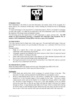
2 1,2 and 3 Grain Thrust (Seconds)Thrust (Pounds)4, 5 and 6 Grain Thrust (Seconds)Thrust (Pounds) You will see that we ve added a number to the front of the standard Motor type code System . This number indicates the total impulse of the Motor in Newton-seconds. For example, 800J360-15A is an 800Ns J Motor , with 360N average thrust and a 15s adjustable delay Assembly and Operating Instructions Step 1 Time Delay Adjustment Each Motor is equipped with a full-length delay grain which provides the delay time shown in the Motor designation. This delay may be reduced by 3,5,7, or 9 seconds as required down to the minimum delay time allowed for the Motor type. Refer to the following table to select the proper adjustment for your application: Delay adjustment and resulting delay time: Delay designation in Motor type code: None -3 -5 -7 -9 -12A 12s 9s 7s 5s 3s -13A 13s 10s 8s 6s 4s -15A 15s 12s 10s 8s 6s NOTE: The ejection charge on all Pro38 motors is of FFFFG black powder.
3 If additional ejection charge is required, do not remove white cap. Instead, add additional powder on top of white cap and seal cavity with tape. Remove the delay/ejection module (Figure 1) from the reload kit liner. Return the reload kit to the package and store safely away during the delay adjustment operation. Check the drill guide and drill holder (Figure 2) for debris and clean if required before proceeding. Select the delay adjustment desired, rotate the drill holder to the appropriate notch in the drill guide and seat the drill holder tab into the drill guide notch. Holding the drill guide and drill holder together in one hand, insert the delay module into the drill guide cavity until the drill bit touches the delay material.
4 Rotate the drill holder clockwise while applying light pressure. Drill into the delay material until the drill guide bottoms out against the delay material. Rotate the drill for several more revolutions in order to clear the delay material from the hole. Remove the delay module from the guide. Empty any residue from the module. For safety, we recommend that you dispose of the delay residue by soaking it in water for a minimum of 1 hour then discarding the residue. A small zip-lock bag or plastic container filled with water is ideal and will safely dissolve the oxidizer from the delay material. This aqueous solution is not harmful to septic or sewage systems. NOTE: If using an electronic recovery System , remove the white plastic disc from the end of the delay/ejection module and transfer the powder to your remote ejection charge holder and follow the recovery System instructions.
5 Reinstall the module into the reload assembly. CAUTION Work in a tidy area, away from other Rocket motors and materials, well away from any open flame or heat source. Perform delay adjustments in the field during Rocket preparation. Delay adjustments are irreversible, and safer if done outside. WARNING Read and follow the Safety Code of the Tripoli Rocketry Association (TRA). Comply with all Federal, State and local laws in all activities with High-Power rockets. Shunt Cap Motor Casing Delay/Eject Module Reload ModuleIgniter Nozzle Cap Figure 1. Pro38 Components Figure 2. Delay Adjustment Delay/Eject Module Drill Guide Drill Holder 384-I205-15A 244-H153-15A 133-G69-12A 765-J330-16A 648-J285-15A 512-I285-15A Igniter Sleeve Step 2 Motor Assembly Inspect the Motor casing for damage.
6 Discard if damaged. Modification of the casing can cause property damage or result in serious personal injury. Leave the protective cap on the nozzle until you are ready to install the igniter. Using a gentle twisting motion, insert the delay/ejection module into the forward end of the plastic liner as far as it will go. A small gap between the forward end of the liner and the shoulder on the delay/ejection module as shown (Figure 3) is normal. Insert the reload kit into the rear end of the Motor casing and thread into the casing. Tighten firmly by hand. The assembly is designed to have a small gap between the thrust ring and the rear end of the Motor casing. If the gap (Figure 4) is more than 1/16 ( mm), check the assembly carefully and re-assemble.
7 Note: if you find assembly difficult by hand, you may carefully grip the reload kit thrust ring with slip-joint pliers for assembly or removal. Step 3 Igniter Installation Carefully uncoil the igniter leads. Remove any kinks or twists and straighten the wires for about 24 (60 cm) from the igniter head. Remove the yellow nozzle cap from the Motor and feed the shunted ends of the igniter leads through the inside of the nozzle cap and out through the hole. Remove igniter sleeve. Insert the igniter head into the nozzle and push until it stops against the top of the Motor core. With the igniter in this position, bend a loop into the igniter leads one cap length from the nozzle exit (Figure 4). Slide the nozzle cap up to the loop made in the previous step and firmly push the yellow nozzle cap over the nozzle to retain the igniter.
8 Remove the shunt and separate the wire leads ONLY while the Rocket is installed on the pad and the launch control System is rendered safe ( disarmed and shunted where applicable). Step 4 Post Firing Unscrew the reload kit from the Motor casing and discard - there are no reusable parts. If the delay module remains in the Motor casing after removal of the reload assembly, push it out through the forward end of the Motor case with a wooden or plastic tool. Be careful not to dent or scratch the Motor casing in any way. The use of metal tools is NOT recommended. Ordinarily, the Motor casing will not require any post-flight cleanup. In the event that any combustion residue remains, the casing should be cleaned as soon as possible with hot soapy water and a non-abrasive cloth.
9 When not is use, store the Motor casing in its original package for protection. Care must be taken not to dent the Motor casing or to damage the internal threads. MEANS OF DISPOSAL: Remove forward closure and remove propellant grains from plastic liner. Discard plastic liner and nozzle assembly. Place forward closure and grains in a shallow hole in the ground, away from any combustibles, install igniter in forward grain in contact with the igniter pellet, secure with tape if necessary. Ignite electrically from distance of 10 meters (min). Wait until flames cease. Remnants may be disposed of with household garbage. First Aid: If ingested, induce vomiting. Burns from flames are to be treated as regular burns with normal first aid procedures.
10 In either case, seek medical attention. Cesaroni Technology Incorporated ( CTI ) certifies that it has exercised reasonable care in the design and manufacture of its products. We do not assume any responsibility for product storage, transportation or usage. CTI shall not be held responsible for any personal injury or property damage resulting from the improper handling, storage or use of their products. The buyer assumes all risks and liabilities and accepts and uses CTI products on these conditions. No warranty either expressed or implied is made regarding Pro38 products, except for replacement or repair, at CTI s option, of those products which are proven to be defective in manufacture within one (1) year from the date of original purchase.