Transcription of Probabilistic Fundamentals Workshop Course Materials ...
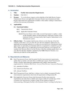
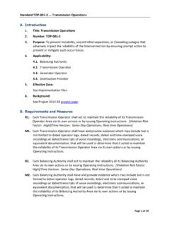
1 01. Develop an expression for the reliability of the following system. Calculate the system reliability if all the components have a reliability of probability and Reliability Concepts1234655555 RedundantRedundant3/5 system1 basic probability and Reliability Concepts RS [R1(R2R3 R4 R2R3R4) R6 R1R6(R2R3 R4 R2R3R4)] [R55 5R54Q5 10R53Q52] R RS [ ( ) ( )][ ] [ ][ ] (a) Calculate the availability of the following system if each component has a failure rate of 5 f/yr and an average repair time of hours.(b) Estimate the system availability using minimal cut probability and Reliability Concepts12346 InputOutput53 basic probability and Reliability ConceptsRs=Rs(4 is good)R4 + Rs(4 is bad)Q4Rs=Rs(3 is good)R3 + Rs(3 is bad)Q3=(R1 + R5 -R1R5) R3 + (R5R6) Q3 Given 4 is goodRs=R1R2R3 + R5R6 -R1R2R3R5R6 Given 4 is badRs=R4[(R1 + R5 -R1R5) R3 + (R5R6) Q3]+Q4[R1R2R3 + R5R6 -R1R2R3R5R6]Substituting4 basic probability and Reliability ConceptsComponent Unavailability = Q = 55 95 availability = ( )[ ] + ( )[ ]= Unavailability = CutsProbability1, , , , 4, , 4, , 4, Unavailability Availability probability and Reliability Concepts01.
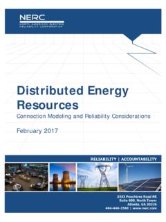
2 Develop an expression for the reliability of the following system. Calculate the system reliability if all the components have a reliability of probability and Reliability Concepts1234655555 RedundantRedundant3/5 system12. (a) Calculate the availability of the following system if each component has a failure rate of 5 f/yr and an average repair time of hours.(b) Estimate the system availability using minimal cut probability and Reliability Concepts12346 InputOutput5 Generating Capacity Reliability Evaluation1. A generating system contains three 25 MW generating units each with a 4% FOR and one 30 MW unit with a 5% FOR. If the peak load for a 100 day period is 75 MW, what is the LOLE and LOEE for this period. Assume that the appropriate load characteristic is a straight line from the 100% to the 60% Capacity Reliability Evaluation13 -25 MW units U = -30 MW units U = Capacity Reliability Evaluation2IC=105 MW75 MW45 MW0100 daysTotal CapacityCap OutProbabilityTime (hrs)Energy (MWh) , , , , , Capacity Reliability EvaluationGenerating Capacity Reliability Evaluation4 nkkktpLOLE1= hrs/100d period nkkkEpLOEE1= MWh / 100 day period5 Generating Capacity Reliability Evaluation Loss of Load Expectation, LOLE = hrs/100 d period Loss of Energy Expectation, LOEE = MWh/100 d period Energy Index Reliability EIR = Energy Index of Unavailability EIU = Units per Million UPM= 1614 System Minutes SM = 1 ,000 60 Two power systems are interconnected by a 20 MW tie line.
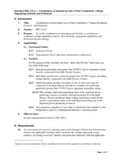
3 System A has three 20 MW generating units with forced outage rate of 10%. System B has two 30 MW units with forced outage rates of 20%. Calculate the LOLE in System A for a one-day period, given that the peak load in both System A and System B is 30 Capacity Reliability EvaluationAB20 MW3-20 MWU= MW2-30 MWU= MW7 Generating Capacity Reliability EvaluationSystem ACap BCap Capacity Reliability Evaluation8 Capacity Array ApproachSystem B03060 System (A)[Single System] = days/dayLOLE(A)[Interconnected System] = days/dayGenerating Capacity Reliability Evaluation9 Equivalent Unit ApproachCap MW Assisting UnitModified System A IC = 80 MWCap OutProbabilityCum. (A)[Interconnected System] = days/dayGenerating Capacity Reliability Evaluation1. A generating system contains three 25 MW generating units each with a 4% FOR and one 30 MW unit with a 5% FOR. If the peak load for a 100 day period is 75 MW, what is the LOLE and LOEE for this period.
4 Assume that the appropriate load characteristic is a straight line from the 100% to the 60% Two power systems are interconnected by a 20 MW tie line. System A has three 20 MW generating units with forced outage rate of 10%. System B has two 30 MW units with forced outage rates of 20%. Calculate the LOLE in System A for a one-day period, given that the peak load in both System A and System B is 30 Capacity Reliability EvaluationAB20 MW3-20 MWU= MW2-30 MWU= MW1 Transmission System Reliability Evaluation1. Consider the following systemThe supply is assumed to have a failure rate of f/yr with an average repair time of 2 hours. The line data are as follows. 123 ABCS upply42 Transmission System Reliability EvaluationUse the minimal cut set approach to calculate a suitable set of indices at each load RateAverage Repair f/yr8 Cut(f/yr)r (hrs)U (hrs/yr) , , System Reliability EvaluationLoad Point A 123 ABCS upply44 Transmission System Reliability Evaluation Min Cut(f/yr)r (hrs)U(hrs/yr) , , Point B123 ABCS upply45 Min Cut(f/yr)r (hrs)U(hrs/yr)At System Reliability Evaluation Load Point C123 ABCS upply46 Transmission System Reliability EvaluationSummaryMin Cut(f/yr)r (hrs)U (hrs/yr) 123 ABCS upply47 Composite System Reliability Evaluation2.
5 A four unit hydro plant serves a remote load through two transmission lines. The four units are connected to a single step-up transformer which is then connected to two transmission lines. The remote load has a daily peak load variation curve which is a straight line from the 100% to the 60% point. Calculate the annual loss of load expectation for a forecast peak of 70 MW using the following Units 25 MWFOR = 2%Transformer 110 MVA U = lines Carrying capability 50 MW per line Failure rate = 2 f/yr Average repair time = 24 hrs8 Composite System Reliability EvaluationCalculate the LOLE in three stages using the following configurations.(a)(c)(b)9(d) Calculate the LOLE for Configuration (b), if the single step-up transformer is removed and replaced by individual unit step-up transformers with a FOR of (e)Calculate the LOLE for the conditions in (d) with each transmission line rated at 50 MW.(f)Calculate the LOLE for the conditions in (d) with each transmission line rated at 75 MW.
6 (g)Calculate the LOLE for the conditions in (d) with each transmission line rated at 100 MW.(h)Calculate the LOLE for the conditions in (f) with Model 1 common mode TL failure. [ c = f/yr ](i)Calculate the LOLE for the conditions in (f) with Model 3 common mode TL failure. [ c = f/yr, rc= 36 hr ] 10 Capacity OutProbabilityTimeExpectation0 System Reliability EvaluationConfiguration (a)LOLE = days/yr11 Composite System Reliability EvaluationCapacity OutProbabilityTimeExpectation0 (b)LOLE = days/yr12 Composite System Reliability EvaluationConfiguration (c)Transmission lines 2f/yr 1r 876024 365r/yr Unavailability 22 365 Availability OutProbability0 System Reliability EvaluationT/G100755025010010075502505050 5050250000000 System Capacity StatesGeneration In (MW)Transmission-In(MW)14 Composite System Reliability EvaluationCapacityInOutProbabilityTimeEx pectation100 (c)LOLE = days/yr15 Composite System Reliability EvaluationConfiguration (d)Calculate the LOLE for Configuration (b)
7 , if the single step-up transformer is removed and replaced by individual unit step-up transformers with a FOR of unit FOR = + ( )( )U = = System Reliability EvaluationCapacityInOutProbabilityTimeEx pectation100 ,733661 Configuration (d)LOLE = days/yr17 CapacityInOutProbabilityTimeExpectation1 00 (e) Calculate the LOLE for the conditions in (d) with each transmission line rated at 50 = days/yr18 CapacityInOutProbabilityTimeExpectation1 00 (f) Calculate the LOLE for the conditions in (d) with each transmission line rated at 75 = days/yr19 CapacityInOutProbabilityTimeExpectation1 00 (g) Calculate the LOLE for the conditions in (d) with each transmission line rated at 100 = days/yr20(h) Calculate the LOLE for the conditions in (f) with Model 1 common mode TL UpOne DownBothDown2 2 cP(Both Up) = (One Up and One Down = (Both Down) = analysis of Model 1P4= [ 1 2( 1+ 2+ 1+ 2) + c( 1+ 2)( 2+ 1)]/ DD = ( 1+ 1)( 2+ 2)( 1+ 2+ 1+ 2) + c[( 1+ 1)( 2+ 1+ 2) + 2( 2+ 2)] If the two components are identicalP4= [2 2+ c( + )] / [2( + )2+ c ( + 3 )] = P(Both Down) = 2122 The basic reliability indices for Model 1 can be estimated using an approximate method [1].)
8 System failure rate = s= 1 2(r1+ r2) + cAverage system outage time = rs= (r1r2)/(r1+ r2) System unavailability = Us= srsP( Both Down) = calculation for:P(One line Up & One line Down) = 2 AL. UL= 2.(2/367)(365/367)= (Both lines Up) = the generation and transmission = days/year24 Approximate method applied to Model 3 In this case: s= 1 2( r1+ r2) + cUs= 1 2r1r2+ c rcrs= Us/ sP( Both Down) = calculation for:P(One line Up & One line Down) = 2 AL. UL= 2.(2/367)(365/367)= (Both lines Up) = the generation and transmission = days/year26 Composite System Reliability Evaluation(a)Generation (G) only (b)(G) with single transformer (T) (c)G, T and two 50 MW transmission lines (d)(G) with unit transformers (e)Generation only (f)Condition (d) with two 50 MW transmission lines (g)Condition (d) with two 75 MW transmission lines (h)Condition (d) with two 100 MW transmission lines (i)Condition (f) with Model 1 common mode TL failure (j)Condition (f)
9 With Model 3 common mode TL failure d/yConditions27 Composite System Reliability Evaluation2. Consider the following system1. Calculate the probability of load curtailment at load points A and B2. Calculate the EENS at load points A and B2712BA12328 Composite System Reliability Evaluation System DataGenerating *25 MW units *40 MW unitsLoadsA 80 MW B 60 MWTransmission Lines28 1 4f/yr,r 8hrs,LCC 80MW2 5f/yr,r 8hrs,LCC 60MW3 3f/yr,r 12hrs,LCC 50MW29 Composite System Reliability Evaluation Conditions Assume that the loads are constant Assume that the transmission loss is zero Consider up to two simultaneous outages Assume that all load deficiencies are shared equally where System Reliability EvaluationElementAU25 MW MW Element Probabilities /r31 Composite System Reliability Evaluation Plant ProbabilitiesConditionsP(Plant1)P(Plant2 )All Units Unit Unit Lines case analysisSelect a contingencyEvaluate the selected contingencyTake appropriate remedial actionYesYesEvaluate the impact of the problemCalculate and summate the load point reliability indicesCompile overall system indicesYesNoNoNoThere is a system problemThere is still a system problemAll contingencies evaluatedSimulationSampleLoadGeneratorsW eatherTransmissionTrials complete?
10 Basic Structure:33 Composite System Reliability Evaluation12BA1234*25 (100 MW)2*40 (80 MW)(80 MW)(60 MW)(50 MW)(80 MW)(60 MW)Total Cap. 180 MWTotal Load 140 MW34 Composite System Reliability EvaluationStateConditionAB1No Outages----21 G1----31 G1, 1 G1 41 G1, 1 G2 51 G1, L1----61 G1, L2-- 71 G1, L3----81 G2,----91 G2, 1 G2 StateConditionAB101 G2, L1 111 G2, L2 121 G2, L3----13L1,----14L1, L2 15L1, L3----16L2-- 17L2, L3-- 18L3,----35 Composite System Reliability EvaluationStateConditionProbabilityLCEEN S3G1, MWh/yr4G1, , , , , (A) = (A) = MWh/yr36 Composite System Reliability EvaluationStateConditionProbabilityLCEEN S3G1, MWh/yr4G1, , , , , , , (B) = (B) = MWh/yr1 Transmission System Reliability Evaluation1. Consider the following systemThe supply is assumed to have a failure rate of f/yr with an average repair time of 2 hours. The line data are as follows. 123 ABCS upply42 Transmission System Reliability EvaluationUse the minimal cut set approach to calculate a suitable set of indices at each load RateAverage Repair f/yr8 System Reliability Evaluation2.