Transcription of Prodigy RF Installation Guide NOTE: Electronic …
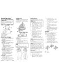
1 PreferredMounting LocationAlternate MountingLocationsCable TowardTow Vehicle 2008 Cequent Performance ProductsProdigy RFElectronic Brake ControlFor 2, 4 and 6 brake applicationsREAD THIS FIRST:Read and follow all instructions carefully before installing or operating the Prodigy RF. Keep these instructions with the Brake Control for future of Prodigy RFA. Power KnobF. 7-Way cable to B. Boost Buttontow vehicleC. Manual OverrideG. Connection to trailerD. DisplayE. Connector to Auxiliary Power PortImportant Facts to Remember1. WARNING The Prodigy RF may operate with reducedperformance if the Remote Hand Held Unit is removedor disconnected while the trailer is in Do not mount or activate RF generating items (cellphones, two way radios) near (less than 12 ) to theHand Held Unit or Power The Prodigy RF employs an inertial sensor. It sensesdeceleration and generates an output that is based ondeceleration, thus the term Proportional Braking.
2 4. The Prodigy RF will HOLD your trailer with 25% ofpower setting while you are at a standstill with brakepedal applied for longer than 5-7 seconds. 5. The Prodigy RF will brake proportionally in reverse. It will apply the appropriate brake voltage based ondeceleration. 6. WARNING The Gross Combined Weight Rating(GCWR) must never exceed the vehicle CAUTION This control is not designed for use withelectric-hydraulic trailer brake CAUTION Do not submerge or immerse Prodigy RF in For Technical Assistance and Warranty Information call:1-888-785-5832 or GuideTrailer Mount Power ModuleMounting InstructionsWARNING The Prodigy RF Power Module mustbe securely mounted to the trailer frame. Failure toinstall the Power Module within these constraintsmay cause impaired Power Module can be mounted to any suitable sur-face on the trailer frame.
3 The module cover should beapproximately level, within 5 , and above the trailerframe rail. Preferred mounting location is on the side ofthe trailer frame rail with the 8 foot cable towards thetow Select a location so that the Power Module s coveris in the UP Use the four 1/4 14 x 1-1/4 self drilling screws(provided) to drill into the trailer frame. Snugscrews securing Power Module. Tamper ResistWasher Head Screws may be used for added Secure the excess 7-Way tow vehicle and Use of different screws may damagethe Power Module, or may not provide Do not mount in a concealed location,or inside a metal part of the trailer. Do not placeinside a utility box mounted on the Do not mount in a location that willinterfere with a load equalizing Power ModuleYour Prodigy RF Power Module has a molded Bargman 7-Way cable that will plug into the tow vehi-cle.
4 Refer to Wiring Diagram for location of pins andfunction. When all connections are made, this connec-tion supplies all power and signals to both the PowerModule and to the trailer. The trailer 7-Way cable isconnected directly to the 7-Way connector on the rear ofthe Power Module. There is no additional wiring neces-sary on the Tow vehicle Must be Capable of pro-viding 12V @ 20A for Electric Brake Applications,Up to 6 brakes (3 axles).CAUTION The Battery Charge to the trailer maybe temporarily disconnected (approximately 5 min-utes) during braking if the total current to the Trailer(Battery Charge and Electric Brake) exceeds 20 Amps. This allows for full brake power withoutexceeding the tow vehicles wiring Ground2 Electric Brake3 Tail & License4 Battery Charge5 Left Stop & Turn6 Right Stop & Turn7 Center Auxiliary4762351 Remote Hand Held UnitPlug the Hand Held Unit into any suitable 12 VAuxiliary Power Port in the vehicle.
5 Remote Hand Held Unit must be within easy reachof the operator. Do NOT operate with the Remote Hand Held :Some factory wired tow vehicles disconnectthe Battery Charge output in the 7-Way connectorwhen the ignition is turned off. This will turn off thePower Module and the Hand Held Unit will display Readings after Connecting the Prodigy RFOnce the units are connected and successfully paired,you should see the following on the two digit display : Initial Power to the Hand Held, without pairing or Power Module not powered or Paired, but Trailer is not connected to PowerModule. Power to Prodigy RF with trailer connected and Manual Override Activated without trailer connected. Manual Override activated (with trailer), denotesa hypothetical power output. This value is set usingthe power knob. Range is to 13 volts. This is anindication of voltage output to electric brakes.
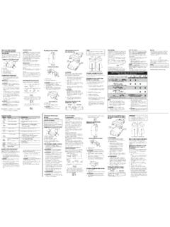
6 display will be blank during power saving mode (nomotion or brakingactivity for at least 2hours)Boost feature notengaged.(BlankDisplay)Pairing InstructionsSynchronization of the Remote Hand Held Unit to thePower Module:1. Connect trailer to tow Plug the Power Module 7-Way cable into the Trailer s 7-Way connector must be disconnectedfrom the Power Start vehicle s engine. (Some vehicles require KeyOn to supply power to the 7-Way connector orAuxiliary Power Port)5. Plug the Remote Hand Held Unit into an auxiliarypower source within easy reach of the Turn the Power Knob to minimum position,Flashing Fully depress and hold both the MANUALOVERRIDE and BOOST BUTTON. The displaywill start from and end at Once has been achieved, the Manual and Boostcan be Press and hold the brake pedal until the displayshows flashing for a correct Set the Power Knob to greater than now flashes (not connected).
7 10. Re-connect the Trailer 7-Way connector to thePower Module. display should now be .c. (connected). NOTE: To properly identify your trailer during pairing, the 7-Way trailer plug must be disconnectedfrom the Power Leveling of the SensorThe Prodigy RF will automatically acquire the properlevel setting of the tow vehicle and trailer combinationduring the pairing DiagramFLASHINGEGFDCBAR emote Hand Held UnitTrailer MountPower ModuleP/N 4747 REV A10/08 Adjusting the Power to the Trailer Brakes (Prior to setting Boost)Once the Power Module has been securely mounted tothe trailer frame and paired to the Hand Held Unit, it isnecessary to set the power needed to stop the trailerduring a braking Connect trailer to tow Verify the Power Module to the Hand Held Unithave been Verify that all tow vehicle and trailer cables havebeen properly Verify proper operation of all towvehicle and trailer lights prior to With the engine running, and the Manual Overridefully depressed, set the Power Knob to indicateapproximately , then release the Drive tow vehicle and trailer on a dry level pavedsurface at 25 mph and fully apply ManualOverride.
8 If trailer brakes lock up: Turn power down using power knob. If braking was not sufficient: Turn power up using power Repeat Step (6) until power has been set to a pointjust below wheel lock up or at a force sufficient toachieve maximum braking Using the brake pedal, make a few low speed stopsto check the power setting. Trailer braking is initi-ated and terminated via signals on the trailerwiring, (Left and Right Turn and Stop). When thebrake pedal is released, the trailer braking willcease.(Boost Setting continued)[ ],during a braking event, the power automaticallystarts out at approximately 13% of the power setting andincreases with deceleration. With the boost on level 2,[ ],or with the boost on level 3, [ ],during abraking event, the power automatically starts out atapproximately 25% of the power setting and increaseswith cases where you might want to use the boost button: You like the trailer braking to LEAD the tow vehicle s braking Towing a full vs.
9 Empty trailer Degraded brake performance (most electric brakesrequire manual adjustment - see Appendix A or a dealer for adjustment or repair) NOTE: Boost not intended to be used to take place oftrailer brake adjustment or the chart below for recommended Boost settings (indicated with X) for typical Trailer to Vehicle weight your boost setting based on your towing situation,driving preference and condition of your trailer Boost Settings For Optimal Performance (with properly adjusted trailer brakes*)TRAILER WEIGHT compared to VEHICLE WEIGHTT railer weighs LESS than VehicleTrailer weighs APPROXIMATELY SAMEas VehicleTrailer weighs UP TO 25% MORE than VehicleTrailer weighs UP TO 40% MORE than VehicleTrailer weighs OVER 40% MORE than VehicleXXXXXXXXXXXWARNING Do not exceed GrossCombined Weight Rating (GCWR)* Increased Boost setting may be needed if trailer brakes are worn, see Appendix A or a dealer for brake adjustment or BOOST LEVEL BOOST OFF Boost SettingThe boost button was designed to allow a more aggressivesetting for your trailer brakes and is available in three lev-els - [ ], [ ], [ ].
10 Each incremental boost settingincreases the sensitivity of the Prodigy RF s inertial sen-sor, enhancing the participation of the trailer brakes duringa braking first press on the boost button displays the current set-ting. Boost is advanced to the next level by continuing topress the boost seconds after setting the boost level, the display willshowindicating Boost Onby the right most example: With the boost off, [ b.],during a brakingevent, the power to the brakes starts out at zero andincreases with deceleration. With the boost on level 1, Boost power may need to be adjusted for differentload weights and road all trailer brakes will lock up due to variousconditions. However, inability to lock up thebrakes generally indicates the need for an inspection to determine the the power is set correctly you should feelunified braking between the trailer and tow : warm the trailer's brakes before setting the power.