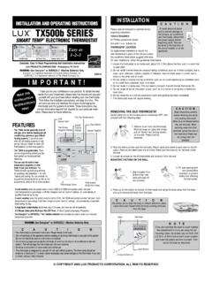
Transcription of PRODUCT INSTALLATION MANUAL TX700U Universal …
1 This thermostat can be used with most 24 volt: gas, oil, Millivolt, electric heating and cooling systems,including heat pumps with an aux/emerg heat cannot be used with: 120/240 volt heating elements (without a transformer), or on heat pumps thathave two compressor stages (Y2). Ask your dealer for other LUX thermostats to control those systems. The thermostat requires batteries to operate and failure or sub-standard performance of the batteriesmay impair or prevent the correct operation of the thermostat. Use Duracell or Energizer alkalinebatteries ONLY for all LUX thermostats requiring batteries.
2 BE SURE TO CHANGE THE BATTERIES ATLEAST ONCE A YEAR, or whenever you see the LO BATT indication on the screen. Failure to followthese battery instructions could result in property damage and/or personal injury. The electrical rating for this thermostat is Amps per terminal, with a maximum total load of all terminals combined. The thermostat contains parts that may wear out through use and are susceptible to failure if over-loaded or used in a manner other than as indicated in the documentation. Check unoccupied residences regularly to ensure that all systems are operating properly.
3 Check any heating/air-conditioning system including this PRODUCT before operation and at regularintervals. Electrical interference, static electricity, failure or substandard performance of batteries, wiringdefects in the INSTALLATION and/or characteristics of the connected HVAC devices may prevent thesystem from regulating heating and cooling as anticipated. The thermostat is a sensitive device and dropping the PRODUCT can cause damage to criticalcomponents. If the PRODUCT is dropped or shaken violently during transport or INSTALLATION then itshould be replaced immediately.
4 Persons with physical or mental limitations may not be able to promptly respond to a malfunction ofthe heating/air-conditioning system. All residents should be made aware of the potential in any system for malfunctions that could causecontinuous heating or cooling and should be familiar with the operation and location of theheating/cooling appliance on/off switch. Read the instruction MANUAL completely before installing the thermostat. A more detailed productmanual is available on our website. You should consult a qualified HVAC technician or an electrician if you do not fully understand the INSTALLATION Turn OFF the electricity to all heating and cooling components.
5 Do not turn the electricity back onuntil all work is Write down the letters printed near each wire terminal that is used, and also the color of each wirethat is connected to it. Self-adhesive wire labels are also Carefully remove the wires one at a time, and bend them in a manner so that they do not fall backinside the wall. Do not allow bare wire ends to touch each the wiring diagrams shown on the back of this INSTALLATION sheet to find the closest match to yourparticular heating and/or cooling system. Please read ALL of the Wiring Diagram Notes that are shownabove the connection diagrams, to avoid causing damage to your system or the new Strip wire insulation leaving only 3/8 in.
6 ( ) bare wire ends, and clean off any Fill the wall opening with non-combustible insulation to prevent drafts from affecting thethermostat s normal Route the wires through the opening in the new thermostat base plate, and install the If the previous holes cannot be used, hold the thermostat base against the wall so that it appearsstraight and level (position the base for best appearance) and mark for the new screw holes. Attachthe base to the wall using the screws provided (use the supplied plastic anchors if needed whenmounting to a soft material such as drywall).
7 5. When attaching the wires to the thermostat, please ensure that the bare wire ends are held ALL theway into the terminal block while the screw is being tightened, and be careful not to over tightenthem, as they only need to be / ELEC CIRCUIT BOARD OPTION ( G TERMINAL FAN OPERATION):This setting is a plasticshorting cap called a jumper. This jumper must remain installed, and set to either GAS or ELECTRIC foryour system to work properly. This setting changes how your system s blower fan (if applicable) iscontrolled while the thermostat is in HEAT or EMERG HEAT mode, when the Fan switch in the AUTO position.
8 This setting does not affect the fan operation while in COOL set to GAS , the blower fan is controlled solely by theheating system itself. Systems that would typically use the GAS setting would be: natural gas, propane, or oil furnaces, and : If your blower fan does not operate properly afterinstallation, move the Gas / Electric option to the Electric set to ELEC , the blower fan is controlled directly by thethermostat. This setting is required for heating systems that do notcontrol their own fan, such as HEAT PUMPS, and units that onlyhave an electric-resistive heating element as the heat / OFF / COOL, SYSTEM MODE SWITCH:Set this switch to HEAT to control your heating system,and COOL to control your cooling system.
9 The OFF position will disable both the heating and / ON, FAN MODE SWITCH:When in AUTO, the blower fan (if present in your system) will cycle onand off only while heating or cooling. In the ON position, the blower fan will run constantly at all timeswith or without a demand for heating or , SET SLIDE SWITCH:This provides easy access to common settings, and shouldalways remain in RUN unless a specific item is being adjusted. NOTE: when thermostat is set to MANUAL non-programmable mode, all 4 switch positions will act like RUN, except the AIR FILTER / DOWN BUTTONS:The UP and DOWN buttons are used to control the set temperature, or adjust anyother on-screen items.
10 Typically, an item that is flashing can currently be BUTTON:This button activates and deactivates the MANUAL Temperature Hold feature, whichmaintains a fixed set temperature indefinitely without following a program BUTTON:For Heat Pump systems: this button activates Emergency Heat mode and prevents theoutdoor unit from running. For conventional (non-Heat Pump) systems, this button will have no effect inNormal RUN BUTTON:This is used when setting items such as software options, and temperature items on the screen are flashing during adjustments. Pressing the NEXT button will cycle throughwhich item is BATTERIES INTO THERMOSTAT: Install two brand new Energizer or DURACELL AA sizealkaline (only) batteries, into the thermostat s battery compartment.