Transcription of PRODUCT SPECIFICATION FOR A 15 TO 1,250kVA …
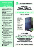
1 PRODUCT SPECIFICATION FOR A 15 TO 1,250kVA . THREE PHASE POWER system . with REGULATION AND conditioning . (Life Line Regulator). General This SPECIFICATION covers the physical, electrical and environmental characteristics and general requirements for a three phase power regulating/ conditioning system . The specified equipment herein shall be referred to as a LIFE LINE . The LIFE LINE includes all components and systems required to install, operate and maintain the system . The systems shall be a zero current tap switching regulator technology. Applicable Documents The National Electrical Code NFPA 1984. (Latest Edition). American National Standards Institute Corp. and its applicable standards , , C89, FCC Part 15, Sub-Part J, Class A. IEC 435 International Electrotechnical Commission Recommendation "Safety of Data Processing Equipment". VDE 0804 Verbauch Deulscher Elektotechiker standard. Telecommunication and Electronic Data Processing Unit and Systems".
2 UL 1950 Underwriters Laboratories, Inc. Standard for Safety. VDE 0806 Verbond Deutscher Electrotechniker Standard "Safety Design". CSA Canadian Standards Association, "Data Processing Equipment". NEMA National Electrical Manufactures Association and its applicable standards. Local Inspection Authorities having jurisdiction over electrical equipment and its installation. Major Components The basic components of the LIFE LINE shall consist of: base, case, isolation transformer, regulating electronics, bypass switch, internal wiring, single point ground and EMI shielding and optional indicators, input and output filters, and output circuit protection. system Package and Construction Agency approval. The LIFE LINE shall be UL Listed under standard 1950. Cabinet The cabinet shall consist of the following: 1. Frame The base shall be of heavy gage sheetmetal of a minimum of 14 gage. Each base shall be painted with baked enamel paint of smooth finish.
3 Four holes of a minimum of 9/16 " shall be provided in the base for the purpose of securing it to the floor. 2. Internal Sheet Metal All internal sheet metal attached to the base shall be plated Gold Zinc Wash or galvanized to ensure RFI, EMI susceptibility reduced to the absolute minimum. Minimum thickness shall be 16 gage. 3. Removable Access Panels Page 1 of 5 LFL-2025D-299. Removable front and rear panels shall be provided. 4. Cover A cover shall be provided with a solid top. The top shall be easily removed to provide access to the transformer taps for field changes. 5. Conduit Entry Input and output conduit entry shall be provided in the right and left lower side panels as well as provision for bottom entry. Transformer: 15 to 300kVA. Isolation Transformer: A double-shield, multi-tapped, all copper, baked varnish, convection cooled, delta-wye three phase isolation transformer shall be provided. The isolation transformer shall be mounted on rubber isolation pads to prevent 60Hz hum of the core from being transmitted to the base.
4 The transformer core clamp shall be grounded to the base through a 1" copper strap. The transformer insulation system shall be 220 C. Taps shall be provided on the primary to accommodate the tap-switching electronics. Two temperature monitors shall be provided: 140 C (alarm) and 160 C (shut-down). The construction of the transformer should separate the primary connections and the secondary. The output terminals of the secondary shall be at opposite ends of the coil for the input terminals of the primary to minimize the possibility of transverse mode injection. A copper foil shield shall be provided to allow a large surface area for shunting RFI signals of the core to ground. Full load taps shall be provided (2) FLAN and (4) FLBN for connection of the tap switching regulator module. 400 to 1,250kVA . Buck and Boost Transformer: A double-shield, multi-tapped, all copper, baked varnish, convection cooled transformer shall be provided. The transformer shall be mounted on rubber isolation pads to prevent 60Hz hum of the core from being transmitted to the base.
5 The transformer core clamp shall be grounded to the base through a 1" copper strap. The transformer insulation system shall be 220 C. Taps shall be provided on the primary to accommodate the tap-switching electronics. Two temperature monitors shall be provided: 140 C (alarm) and 160 C (shut-down). The construction of the transformer should separate the primary connections and the secondary connections. The output terminals of the secondary shall be at opposite ends of the coil for the input terminals of the primary to minimize the possibility of transverse mode injection. A. copper foil shield shall be provided to allow a large surface area for shunting RFI signals of the core to ground. Full load taps shall be provided (2) FLAN and (4) FLBN for connection of the tap switching regulator module. Regulation Electronics A solid state, electronic, zero current crossing tap switching regulation system shall be provided. This regulator shall use SCR (Silicon Controlled Rectifiers) technology in its construction and shall be rated at 100% above worst case ratings (26% below nominal) without adverse affect.
6 The regulation system shall respond to a change in the input voltage within one cycle. The electronics shall be separated from the transformer area by a heat shield of sheetmetal. This barrier shall be zinc plated for maximum conductivity. Bypass switch ( Regulation Only ). A manually operated bypass switch shall be provided. In the event that the regulation circuit malfunctions, it shall select the 100% tap of the isolation transformer and provide unregulated nominal power to the output circuit. Access to the bypass switch shall be through an access plate on the front panel. The bypass switch is a break-before-make switch. Internal Wiring All internal wiring shall be UL Listed appliance wire or power wiring of multi stranded construction. Primary & Secondary Power wiring from the transformer shall not be in close proximity of each other. Single Point Ground (SPG). A single point ground bus shall be provided and shall be of copper construction.
7 Minimum thickness shall be 1/4" X 1/4" and be silver plated to provide connection of the lowest possible resistance to all ground wires secured to the SPG. The following shall be grounded to the SPG: 1. Equipment grounds. 2. Neutral of isolation transformer ( 300kVA). 3. Core of the Transformer. 4. Primary and Secondary shields. Page 2 of 5 LFL-2025D-299. 5. Frame. 6. Equipment grounding conductor from the branch circuit. 7. Case. 8. Regulation Electronics. Input Transient Noise Filter The Input Transient Noise Filter consist of a resistor/capacitor network which acts as a large snubber circuit to eliminate high frequency impulses from entering the power system . Output Transient Noise Filter (OPTIONAL). The Output Transient Noise Filter consists of a capacitor network which is installed on the secondary of the unit. This capacitor network, when coupled with the input filter, virtually eliminates most electronic noise from reaching the applied load or being fed back to the unit from noise generating loads.
8 Output Transient Suppression Network (OPTIONAL). A transient suppression network shall be located on the secondary side of the isolation transformer. The OTSN shall suppress load induced noise to reduce the sensitivity of one load from another load. The OTSN shall have the following characteristics: 1. Parallel (Shunt) Protection. 2. Response time of < 5 ns 3. Repetitive transients up to 5000/sec 4. Clamping Voltage: 160 VAC line to neutral. 274 VAC line to line. 5. Peak Pulse Power Rating: 25 kW line to neutral kW line to line 6. Each device shall be fused for circuit protection. Visual service indicators (one for each phase) shall be provided on the indicator panel of the LIFE LINE to indicate that the OTSN is no longer providing protection. Indicators and Meters (OPTIONAL). The following indicators shall be provided: 1. Power On: There shall be one indicator for each phase which has primary power being supplied to it. 2. Service Required: Indicators shall be provided to indicate the status of the output transient suppression network fuses.
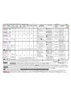
9 The indicator shall be illuminated any time any of these fuses are open. Electrical Characteristics 60 Hz Frequency units: 1. Output Rating kVA: 15, 30, 50, 75 100, 125, 150, 175, 200, 225, 250, 300, 400, 500, 625, 750, 875, 1000, 1250. 2. Input Voltage: 208 VAC (15 to 500kVA only) or 480 VAC. 3. Output Voltage: 208Y/120 VAC or 480Y/277 VAC. 4. Input Frequency Tolerance: 3 Hz Transformer 1. Type: Dry, isolation, multi-shield, copper wound, three phase, computer grade. 2. Impedance: 2% to 5% maximum 3. Efficiency: 96% @ full load 4. Load Power Factor: Unity to leading or lagging 5. Harmonic distortion: < 1% maximum added 6. Wave form distortion at tap switching: < 1% added 7. Noise Rejection (typical): Common mode: -120 dB ( to 10 MHz ) (15 to 300 kVA only). Normal Mode: -20 dB/decade ( 1 KHz to 10 MHz ) (OPTIONAL 60dB/decade). Page 3 of 5 LFL-2025D-299. Audible Noise: Meets or exceeds NEMA standards Input Voltage Regulation: +10% to -26% of nominal Output Voltage Regulation: 3% Typical, 4% maximum for all load and line conditions.
10 Response Times: 1 cycle typical Load Rating: Continuous regardless of line / load conditions. Page 4 of 5 LFL-2025D-299. Overload Inrush Rating: 200% of full load for 10 seconds 1000% of full load for 1 cycle Physical characteristics Dimensions 208 VAC INPUT. KVA. 15-30 50-75 100-300 400-500 625-1250. Height N/A. Width N/A. Depth N/A. 480 VAC INPUT. KVA. 15-30 50-100 125-150 175-300 400-875 1000-1250. Height . Width . Depth . Operating Environment Temperature: 32 F to 122 F ( 0 to 50 C ). Humidity: 10% to 90% relative humidity, without condensation Altitude: 0 to 7000 ft. Storage Environment Temperature: -4 F to 140 F ( -20 C to 60 C ). Humidity: 0% to 100% relative humidity, without condensation Warranty The manufacturer shall warrant the LIFE LINE to be free from defects in both materials and workmanship for a period of 24 months from time of installation or 30 months after shipment, which ever occurs first. Manufacturer's Qualifications The LIFE LINE shall be furnished by a manufacturer who specializes in the manufacturing of Regulating/ conditioning Systems, has been in business for at least 15 documented years, and with a nation wide service organization.