Transcription of Professional reference guide 21dec07
1 11 Professional reference guide updated 21dec07 INDEX Pg. contents 1. Index 2. How thermostats work 3. Thermostat general wiring chart 4. Heat pump operation 5. 2 Wire Heat, Gas millivolt system wiring 6. 2 Wire Heat, 24 VAC wiring 7. 3 Wire Heat, and Fan wiring 8. 4 Wire Heat, Fan, and Cool 9. 5 Wire Heat, Fan and Cool (two power wires) 10. 5 Wire 2 heat, fan, and cool 11. 4 Wire Heat Pump (without auxiliary heat) 12. 5 Wire Heat Pump (with auxiliary heat) 13. Zoned Forced Air Heating and Cooling 6 wire (main) 3 wire (remotes) 14. Zoned hot water systems 3 wire 15. RV, Swamp coolers, Mobile Home systems 16. Line Voltage thermostats (single pole and double pole) 17. Line voltage cooling and Controlling humidity 18.
2 Humidifying 19. De-humidifying using the A/C or using an external de-humidifier 20. De-humidifying (using an External humidistat) 21. Thermostat Power (and remote power) 22. Fan control: Manual, heating, cooling 23. General Information: swing, anticipator, accuracy, calibrate room temp 24. General Info continued: Compressor delay, differential, reset 25. Trouble shooting: fan, heat, compressor, 24 VAC, Short cycle 26 Test long cycling, fan not running, random resets, B wire info. 27. Safety 22 THERMOSTATS FOR HVAC (heat, ventilation, air conditioning) A thermostat is an electronic switch much like a light switch, , the switch is either ON (contacts closed) or OFF (contacts open). In a thermostat this is done several ways.
3 1. The old mercury thermostats use a vial of mercury. When the vial is tipped one way, the mercury closes two contacts at that end by touching them both. When the vial is tipped the other way, it opens those two contacts. The vial of mercury is connected to a bi metal spring that reacts to temperature tipping the vial back and forth. The use of mercury is no longer acceptable, but there are many still in use. Dispose of mercury very carefully as it is extremely dangerous. Call your local recycler to find a disposal station. 2. Some mechanical thermostats use a bi metal device that causes the two contacts to touch or open depending on temperature. 3. Modern electronic thermostats use what is called a magnetic latching relay. This is a device that has two contacts that close when a coil on the relay is pulsed with a voltage.
4 To open it, a second coil is pulsed and the contacts open. The voltage pulses are generated by the electronics inside the thermostat. The electronics is what makes thermostats different from each other. The purpose of most thermostats is to close two contacts to turn on an HVAC function and to open them to turn off that function. There are 3 main power sources used for switching HVAC functions on and off, Gas Millivolt (750mv), 24 VAC and line voltages of 115 VAC or 230 VAC. 1. The Gas millivolt system requires the thermostats to switch only about 750Mv (3/4 volt) to turn on and off the gas heat. Any 24 VAC thermostat can be used. 2. The 24 VAC systems require the thermostat to switch 24 VAC. All low voltage thermostats will easily switch these two systems on and off.
5 This is the most popular. These cannot be use for line voltage heating or cooling. 3. The 115 VAC or 230 VAC is used for electric baseboard, wall heaters, or ceiling heat; this takes a special LINE VOLTAGE Thermostat. If the old thermostat has 2 or 4 large, stiff wires, coming out of a plastic or metal box in the wall (J box), it is likely the system is 115/230 VAC, and must use a line voltage thermostat. Connecting line voltage to a 24 VAC thermostat is dangerous and will severely damage the thermostat. Always shut off power before replacing any thermostat. Standards for identifying low voltage thermostat wiring are set by the National Electrical Manufacturers Association (NEMA) Standards Publication DC 3-2003. These standards set down what letters to be used for what function in thermostats.
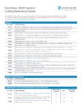
6 Though many thermostats adhere to those standards, some thermostats do not. Below is a wiring chart to help compare wiring letters in most systems. As we discuss various HVAC systems, we will be using the NEMA standard letters for our thermostats. Refer to this chart when replacing old thermostats that do not have the same letters as the Ritetemp thermostats. There is no standard for wire colors. 33 VERY IMPORTANT NOTICE!! BEFORE REMOVING WIRES FROM THE OLD THERMOSTAT, LOOK AT THE LETTERS NEXT TO EACH WIRE AND MARK THE WIRES WITH THE SUPPLIED LETTERS. USE THE CHART BELOW TO CROSS reference . ANY WIRES THAT WERE NOT CONNECTED TO THE OLD THERMOSTAT OR NOT USED ON THE NEW THERMOSTAT SHOULD BE TAPED OFF AND PUSHED BACK INTO THE WALL.
7 THERE IS NO COLOR CODE FOR THERMOSTAT WIRES THOUGH THE COLOR OF THE WIRE MAY MATCH THE LETTER OF THE WIRE, THE COLORS THEMSELVES SHOULD NOT BE CONSIDERED. OLD THERMOSTAT NEW THERMOSTAT (NEMA standard) DESCRIPTION WIREING FOR NORMAL HEATING AND COOLING (gas/oil/elect) (no heat pump) R, or RH, or 4, or V RC/RH (connected) Single power wire W or H W Heat return W2 or H2 W2 2nd stage of heat W3 W3 3rd stage of heat Y or M Y Cool return (compressor) Y2 Y2 2nd stage of cool Y3 Y3 3rd stage of cool G or F G Fan return C or X C 24 VAC thermostat power FOR SEPARATE HEAT AND COOL POWER, REMOVE THE RH/RC JUIMPER AND WIRE AS SHOWN BELOW.
8 RH and R RH to RH and R to RC RH = Pwr heat and R= Pwr cool 4 and R 4 to RH and R to RC 4 = Pwr heat and R = pwr cool RH and RC RH to RH and RC to RC RH = Pwr heat and RC = Pwr cool WIRING FOR HEAT PUMP R RH/RC (connected) Power Y Y and W Compressor (used for heat and cool) W2 W2 Heat pump Aux heat E W2 Emergency heat O O Changeover (Powered in COOL) or or Do not connect both O and B!
9 B B Changeover (Powered in HEAT) Florida Heat Pump (4 wire aqua) may use W as changeover (connects to terminal O) On a heat pump, if O and B are both present, connect O wire to O terminal and B wire to C terminal (TRANE HEAT PUMP PRODUCTS). Do not connect B wire to B terminal as it may damage the 24 VAC power system. 44 ZONED HOT WATER MOTOR VALVES 5 or R RH Power wire 4 or W or NO W Turn Valve on 6 or Y or NC A Turn Valve off ZONED HOT WATER SOLENOID VALVES R RH power Y or B or N/O W Turn Valve off W or N/C A Turn Valve on Heat Pump Operation To better understand heat pumps, go to a drawing at.
10 Heat pumps are a unique method of heating. Essentially it is a reversible air conditioner. An A/C pumps heat out of the house into an outside air exchanger and into the outside air. A heat pump uses very similar equipment and pumps heat from the outside air into the inside air exchanger and into the house. The heat pump has a reversing valve to go from COOL to HEAT. An AIR CONDITIONER gets less efficient in cooling a house as the outside air gets hotter. Similarly, the HEAT PUMP gets less efficient as the outside air gets colder. AUXILIARY HEAT (for heat pumps) In moderate to cold climates, the heat pump cannot keep the house warm if the outside air gets too cold. Most air exchange heat pumps have an additional heat source called AUXILIARY heat and is often electric heat strips but can be GAS or OIL.