Transcription of Programmable 6AL-2 Ignition Control PN 6530 - Holley
1 Note: Solid core spark plug wires cannot be used with an MSD Ignition Control . Note: If you're programming the timing functions of the Ignition , the distributor must be locked Included:1 - Ignition Control , PN 65301 - MSD Pro-Data+ Software4 - Vibration Mounts and ScrewsAccessories:MAP Sensor, see page 6 Hand Held Programmer, PN 7550 Manual Launch RPM Control , PN 7551 WARNING: During installation, disconnect the battery cables. When disconnecting, always remove the Negative cable first and install it last. 3 - Deutsch Connector Harnesses 1 - Mag Pickup Harness, PN 88601 - Parts BagGENERAL INFORMATIONBATTERYThe MSD Programmable 6AL-2 Ignition Control will operate on any negative ground, 12 volt electrical system with a distributor. The MSD can be used with 16 volt batteries and can withstand a momentary 24 volts in case of jump starts. The Ignitions will deliver full voltage with a supply of 9-18 volts and will operate with a supply voltage as low as five your application does not use an alternator, allow at least 15 amp/hour for every half hour of operation.
2 If the engine is cranked with the same battery or other accessories such as an electric fuel or water pump are used, the amp/hour rating should be MSD Programmable 6AL-2 Ignition can be used with most stock coils and aftermarket coils designed to replace the stock coils. There are some "race only" coils such as the MSD Pro Power Coil, PN 8201, that cannot be used with a 6-Series MSD Ignition Control . For more information on recommended coils, consult the supplied Coil Application Chart or check with the manufacturer of your coil. If you have any questions concerning coils, contact our Customer Service Department at (915) Gray Tach Output Terminal produces a 12 volt square wave signal with a 20% duty cycle. Some vehicles with factory tachometers may require a Tach Adapter to operate with the MSD. For more information on Tachometers and MSD Tach Adapters, see the Tachometer Section on page 15. If your GM vehicle has an inline filter it may cause the tach to drop to zero on acceleration.
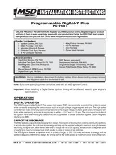
3 If this occurs, bypass the (915) 857-5200 FAX (915) 857-3344 Programmable 6AL-2 Ignition ControlPN 6530 ONLINE PRODUCT REGISTRATION: Register your MSD product online. Registering your product will help if there is ever a warranty issue with your product and helps the MSD R&D team create new products that you ask for! Go to INSTALLATION INSTRUCTIONSMSD (915) 857-5200 FAX (915) 857-3344 spark plugs AND WIRESS park plug wires are very important to the operation of your Ignition system. A good quality, helically wound wire and proper routing are required to get the best performance from your Ignition , such as the MSD Heli-Core or Super Conductor : Solid Core spark plug wires cannot be used with an MSD helically, or spiral wound wire must be used. This style wire provides a good path for the spark to follow while keeping Electro Magnetic Interference (EMI) to a minimum. Excessive EMI, such as the amount that solid core wires produce, will interfere with the operation of the : Correct routing of the plug wires is also important to performance.
4 Wires should be routed away from sharp edges and engine heat sources. If there are two wires that are next to each other in the engine's firing order, the wires should be routed away from each other to avoid inducing a spark into the other wire. For example, in a Chevy V8, the firing order is 1-8-4-3-6-5-7-2. The #5 and #7 cylinders are next to each other in the engine and in the firing order. If the voltage from the #5 wire is induced into #7 detonation could occur and cause engine damage. To add more heat protection to your plug wires, MSD offers Pro-Heat Guard, PN 3411. This is a glass woven and silicone coated protective sleeve that you slide over your plug wires. For extra protection of the spark plug boots, MSD offers Pro- boot Guard, PN plugs : Choosing the correct spark plug design and heat range is important when trying to get the best performance possible. Since there are so many engine combinations and manufacturers, MSD does not recommend which plug or gap is exactly right for your is recommended to follow the engine builder or manufacturer's specification for spark plugs .
5 With that, you can then experiment with the plug gap to obtain the best performance. The gap of the plugs can be opened in " increments, then tested until the best performance is obtained. MSD judges the plug gap by compression and components: MISCELLANEOUS INFORMATIONS ealing: Do not attempt to seal the MSD. All of the circuits of an MSD receive a thick conformal coating of Humi-Seal. This sealant protects the electronics from moisture. If you were to seal the unit, any moisture or water that may seep in through the wiring grommets will not be able to drain and may result in : If you are welding on your vehicle, to avoid the chance of damage, always disconnect both Heavy Power cables of the MSD (You should also disconnect the tach ground wire too).Distributor Cap and Rotor: It is recommended to install a new distributor cap and rotor when installing the MSD Ignition Control . The cap should be clean inside and out especially the terminals and rotor tip.
6 On vehicles with smaller caps, it is possible for the air inside the cap to become electrically charged causing crossfire which can result in misfire. This can be prevented by drilling a couple vent holes in the cap. The holes should be placed between the terminals, at rotor height and face away from the intake. If your environment demands it, place a small piece of screen over the hole to act as a spark : It is normal, yet not very common, for the MSD to produce a spark when the Ignition is first connected to the battery. This is due to the capacitor being examples are just starting points to get you going in the right direction. Every application is different and should be tested and tuned. Compression spark Plug Gap Up to :1: " " :1: " " Above :1: " "INSTALLATION INSTRUCTIONS 3 MSD (915) 857-5200 FAX (915) 857-3344 MOUNTINGThe MSD can be mounted in most positions, except directly upside down (if upside down, moisture or water cannot escape).
7 It can be mounted in the engine compartment as long as it is away from direct engine heat sources. It is not recommended to mount the unit in an enclosed area such as the glovebox. When you find a suitable location to mount the unit, make sure the wires of the Ignition reach their connections. Hold the Ignition in place and mark the location of the mounting holes. Use a 3/16" drill bit and drill the holes for the supplied vibration mounts. Install the vibration mounts, then mount the WIRING INFORMATIONWire Length: All of the wires of the MSD Ignition may be shortened as long as quality connectors are used or soldered in place. To lengthen the wires, use one size bigger gauge wire (12 gauge for the power leads and 16 gauge for the other wires) with the proper connections. All connections must be soldered and : A poor ground connection can cause many frustrating problems. When a wire is specified to go to ground, it should be connected to the battery negative terminal, engine block or chassis.
8 There should always be a ground strap between the engine and the chassis. Always securely connect the ground wire to a clean, paint free metal Resistor: If your vehicle has a ballast resistor in line with the coil wiring, it is recommended to bypass it. ROUTING WIRESThe MSD wires should be routed away from direct heat sources such as exhaust manifolds and headers and any sharp edges. The trigger wires should be routed separate from the other wires and spark plug wires. It is best if they are routed along a ground plane such as the block or firewall which creates an electrical shield. The magnetic pickup wires should always be routed separately and should be twisted together to help reduce extraneous chart shows the polarity of other common magnetic pickups. If using a different magnetic pickup, use the MSD 2-Pin connector, available as PN 8824, for a direct plug-in 1 Common Mag Pickup Mag Pickup WiresDistributor Colors Mag+ Mag-MSD Org/Blk Vio/BlkMSD Crank Trigger Violet GreenFord Orange VioletAccel 46/48000 Series Org/Blk Vio/BlkAccel 51/61000 Series Red BlackChrysler Org/Wht BlackMallory Org/Blk Vio/Blk4 INSTALLATION INSTRUCTIONSMSD (915) 857-5200 FAX (915) 857-3344 WIRING Ignition supply wire, 14-gauge.
9 Connects to battery positive (+) terminal or battery junction. Note: Do not connect to the alternator. Ignition ground, 14-gauge. Connect to battery negative (-) terminal or engine Coil Leads (18-gauge)Orange Connects to the coil positive (+) terminal. This is the only wire that makes contact to the coil positive terminal. Black Connects to the coil negative (-) terminal. This is the only wire that makes contact to the coil negative : High voltage is present at the coil primary terminals. Do not touch the coil or connect test equipment to the terminals while the engine is running or cranking. Trigger Wires(18-gauge)Violet/ Magnetic pickup, 2-pin connector. plugs into an MSD Distributor or Crank Trigger pickup. Violet is positive, Green is negative. When this connector is used, the White and White/Blue wires are not connected. White/ White Trigger input for electronic Ignition amplifiers, an ECU s trigger or points. When this wire is used, the magnetic pickup and White/Blue wires are not con-nected.
10 Red On/Off switch wiring. Connects to a switched 12 volt source. Green2-PinBlue2-PIN CONNECTORH eavyRedHeavyBlack2-PIN CONNECTOR8-PINCONNECTORHall-Effect or ECU trigger. This wire connects to the trigger wire of the Hall-Effect pickup. It can also be connected to an ECU trigger source (low voltage and current). See page 6. When used, the White and Magnetic Pickup wires are not Blue Launch Rev Limit. When 12 volts are applied to this wire it will activate the Launch Rev Limit and reset the Launch Retard. This overrides other rev limits. Light Blue Burnout Rev Limit. When 12 volts are applied the Burnout Rev Limit is active. Gray Tach output. This wire provides a 12 volt, 20 signal that is compatible with most tachs and data acquisition Retard Step. This retard is activated when 12 volts are applied and rpm is above the Step1 Rpm Connector, MAP SensorConnects to an external MAP or gauge pressure +5 volt supplyBrown/Yellow GroundDark Brown Map SignalINSTALLATION INSTRUCTIONS 5 MSD (915) 857-5200 FAX (915) 857-3344 PRESTART CHECK LIST The only wires connected to the coil terminals are the MSD Orange to coil positive and Black to coil negative.