Transcription of Programmable USB Type-C PD Controller - Richtek
1 RT1715 DS1715-04 March 2020 Richtek Technology Corporation. All rights a registered trademark of Richtek Technology Corporation. Sample &BuyPin Configuration(TOP VIEW)WL-CSP-9B (BSC)Ordering InformationNote : Richtek products are : RoHS compliant and compatible with the current require- ments of IPC/JEDEC J-STD-020. Suitable for use in SnPb or Pb-free soldering InformationProgrammable USB Type-C PD ControllerGeneral DescriptionThe RT1715 is a USB Type-C Controller that complieswith the latest USB Type-C and PD standards. The RT1715integrates a complete Type-C Transceiver including theRp and Rd resistors. It does the USB Type-C detectionincluding attach and orientation. The RT1715 integratesthe physical layer of the USB BMC power delivery protocolto allow up to 100W of power and role swap. The BMC PDblock enables full support for alternative interfaces of theType-C : Product CodeW : Date CodeFeatures Dual-Role PD Compatible Attach/Detach Detection as Host, Device or DRP Current Capability Definition and Detection Cable Recognition Alternate Mode Support Supporting VCONN with Programmable OCP Dead Battery Support Low Power Mode for Attach Detection Simple I2C Interface with AP or EC BIST Mode Supported Supported PD except Fast Role Swap Function e-fuse IP 9-Ball WL-CSP PackageApplications Smartphones Tablets LaptopsCC2CC1 VDDSCLSDAVCONNVBUSGNDINT_NA1A2A3B3B1C1C2 C3B2RT1715 Package TypeWSC : WL-CSP-9B (BSC)4 TWRT17152DS1715-04 March Copyright 2020 Richtek Technology Corporation.
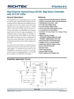
2 All rights reserved. is a registered trademark of Richtek Technology Block DiagramFunctional Pin DescriptionPin No. Pin Name Pin Function A1 CC2 Type-C Connector Configuration Channel (CC) pins. Initially used to determine when an attach has occurred and what the orientation detected. A2 VBUS VBUS input pin for attach and detach detection. A3 VDD Input supply voltage. B1 VCONN Regulated input pin to be switched to correct CC pin as VCONN to power Type-C full-featured cables and other accessories. B2 INT_N Open drain type interrupt output used to prompt the processor to read the registers. B3 SCL I2C serial clock signal to be connected to the I2C master. C1 CC1 Type-C Connector Configuration Channel (CC) Pins.
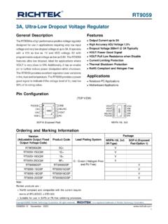
3 Initially used to determine when an attach has occurred and what the orientation detected. C2 GND Ground pin. C3 SDA I2C serial data signal to be connected to the I2C master. VCONNCC1 GNDSCLSDAI2C ControllerFIFOI nternal BusDigital InterfaceVoltage RegulatorPhysical LayerType-C Detection & CC SwitchINT_NVDDVBUSCC2 Register BlockDetectionRP/RD BankRT17153DS1715-04 March Copyright 2020 Richtek Technology Corporation. All rights reserved. is a registered trademark of Richtek Technology Application CircuitReference Part Number Description Package Manufacturer R1, R2, R3 WR04X1001 FTL 1k 1% 0402 WALSIN R4 CR-02FL6---4K7 1% 0402 VIKING C1, C2 0402B331J250 330pF/25V/X7R 0402 WALSIN C3, C4 0402B104K500CT 100nF/50V/X7R 0402 WALSIN Type-C ConnectorCC1CC2 VBUSVDDB attery ChargeControllerVBUSCC1CC2AP/ECSCLINT_NB attery CellOVPVCONNUSB SwitchTRX#1 TRX#2 USB/ FR11kR31kNote : MCU_GPIO-1/MCU_GPIO-2 control DC-DC power IC EN pin for power on/off FTable 1.
4 Recommended Components InformationRT17154DS1715-04 March Copyright 2020 Richtek Technology Corporation. All rights reserved. is a registered trademark of Richtek Technology Portfolio Pin Name Pin Connection Use VCONN VBUS Short to connector VBUS or to connector VBUS (better for surge) CC1 Short to connector CC1 CC2 Short to connector CC2 VCONN Short to DC-DC2 INT_N Pull-high to AP/EC SDA Pull-high to AP/EC SCL Pull-high to AP/EC VDD Short to DC-DC1 Unused VCONN VBUS Short to connector VBUS or to connector VBUS (better for surge)
5 CC1 Short to connector CC1 CC2 Short to connector CC2 VCONN 1k to GND INT_N Pull-high to AP/EC SDA Pull-high to AP/EC SCL Pull-high to AP/EC VDD Short to DC-DC1 Table 2.
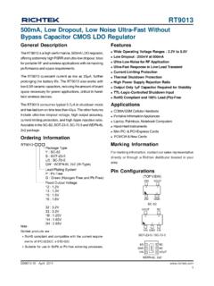
6 Funtion Portfolio InformationNote : If VBUS is shorted between the OVP and Battery Charge Controller , it will occur USB compliance testing failuresand application March Copyright 2020 Richtek Technology Corporation. All rights reserved. is a registered trademark of Richtek Technology On/Off Sequence0 to 10msPower on SequenceVCONN used0 to 10msVDDVCONNINT_N/SDA/SCLPull up VoltagePower on Sequencewithout VCONN used0 to 10msVCONNINT_N/SDA/SCLPull up VoltageVDD0 to 10msPower off SequenceVCONN used0 to 10msVDDVCONNINT_N/SDA/SCLPull up Voltage0 to 10msPower off Sequencewithout VCONN usedVCONNINT_N/SDA/SCLPull up VoltageVDDRT17156DS1715-04 March Copyright 2020 Richtek Technology Corporation. All rights reserved. is a registered trademark of Richtek Technology Characteristics(TA = 25 C, unless otherwise specified.)Parameter Symbol Test Conditions Min Typ Max Unit Common Normative Signaling Requirements Bit Rate fBitRate VDD = 3V to 270 300 330 Kbps Common Normative Signaling Requirements for Transmitter Maximum difference between the bit-rate during the part of the packet following the Preamble and the reference bit-rate pBitRate VDD = 3V to -- -- % Time from the end of last bit of a Frame until the start of the first bit of the next Preamble tInterFrameGap VDD = 3V to 25 -- -- s Time before the start of the first bit of the Preamble when the transmitter shall start driving the line tSt artDrive VDD = 3V to 1 -- 1 s Absolute Maximum Ratings (Note 1)
7 VDD/VCONN------------------------------- ---------------------------------------- ---------------------------------- to 6V CC1/CC2 (Testing Condition : VDD 3V) ---------------------------------------- ------------------------------ to 24V CC1/CC2 (Testing Condition : VDD < 3V) ---------------------------------------- ----------------------------- to 6V VBUS------------------------------------ ---------------------------------------- -------------------------------------- to 28V SDA/SCL/INT_N--------------------------- ---------------------------------------- ---------------------------------- to 6V Power Dissipation, PD @ TA = 25 CWL-CSP-9B (BSC) Package Thermal Resistance (Note 2)WL-CSP-9B (BSC), C/W Lead Temperature (Soldering, 10sec.)--------------------------------- ---------------------------------------- - 260 C Junction Temperature----------------------------- ---------------------------------------- -------------------------- 150 C Storage Temperature Range----------------------------------- ---------------------------------------- ----------- 65 C to 150 C ESD Susceptibility (Note 3)HBM (Human Body Model)---------------------------------- ---------------------------------------- -------------- 2kVRecommended Operating Conditions (Note 4) VDD Input Voltage--------------------------------- ---------------------------------------- -------------------------- to VCONN Input Voltage--------------------------------- ---------------------------------------- --------------------- to (Note 5)
8 VCON Supply Current--------------------------------- ---------------------------------------- ---------------------200mA to 600mA Junction Temperature Range----------------------------------- ---------------------------------------- ----------- 40 C to 125 C Ambient Temperature Range----------------------------------- ---------------------------------------- ----------- 40 C to 85 CRT17157DS1715-04 March Copyright 2020 Richtek Technology Corporation. All rights reserved. is a registered trademark of Richtek Technology Symbol Test Conditions Min Typ Max Unit BMC Common Normative Requirements Time to cease driving the line after the end of the last bit of the Frame tEndDriveBMC VDD = 3V to -- -- 23 s Fall Time tFall VDD = 3V to 300 -- -- ns Time to cease driving the line after the final high-to-low transition tHoldLowBMC VDD = 3V to 1 -- -- s Rise Time tRise VDD = 3V to 300 -- -- ns Voltage Swing VSwing VDD = 3V to V Transmitter Output Impedance zDriver VDD = 3V to 33 -- 75 BMC Receiver Normative Requirements Time Window for Detecting Non-Idle tTransitionW indow VDD = 3V to 12 -- 20 s Receiver Input Impedance zBmcRx VDD = 3V to 1 -- -- M Power
9 Consumption Stand-by Current ISB_Sink Sink current consumption in cable attached VDD = 3V to VDD (Typ.) = mA Low Power Mode ILP_DRP CC toggle at DRP mode when port is unconnected and waiting for connection VDD = 3V to VDD (Typ.) = 10 25 85 A Idle Mode IiIdle_Sink Sink current consumption in Cable attached when disable 24M OSC VDD = 3V to VDD (Typ.) = 100 170 265 A Shutdown Mode Ishutdown The CC pin exposes RD and disables all functions except I2C functions VDD = 3V to VDD (Typ.) = 6 15 40 A VCONN Power IVCONN VCONN current consumption when VCONN without supply to CC VCONN = 3V to VCONN (Typ.) = 5V 6 20 30 A Type-C Port Control Ron for VCONN Switch RON VCONN = 3V to -- 1 VCONN OCP Setting Range IOCP VDD = 3V to , VCONN = to 200 -- 600 mA RT17158DS1715-04 March Copyright 2020 Richtek Technology Corporation.
10 All rights reserved. is a registered trademark of Richtek Technology Symbol Test Conditions Min Typ Max Unit VCONN OCP Range_200mA IOCP_Range_ 200mA VDD = , VCONN = 5V, OCP setting = 200mA 135 205 275 mA VCONN OCP Range_300mA IOCP_Range_ 300mA VDD = , VCONN = 5V, OCP setting = 300mA 240 310 380 mA VCONN OCP Range_400mA IOCP_Range_ 400mA VDD = , VCONN = 5V, OCP setting = 400mA 345 415 485 mA VCONN OCP Range_500mA IOCP_Range_ 500mA VDD = , VCONN = 5V, OCP setting = 500mA 450 520 590 mA VCONN OCP Range_600mA IOCP_Range_ 600mA VDD = , VCONN = 5V, OCP setting = 600mA 555 625 695 mA Time for VCONN Switch to Turn-On VDD = , VCONN = 350 450 620 s Time for VCONN Switch to Turn-On State_5V tSoft_VCCON_5V VDD = , VCONN = 5V 460 540 720 s DFP 80 A CC Current DFP80 VDD = 3V to 64 80 96 A DFP 180 A CC Current DFP180 VDD = 3V to 166 180 194 A DFP 330 A CC Current DFP330 VDD = 3V to 304 330 356 A UFP Rd Rd VDD = 3V to k UFP Pull-Down Voltage in Dead Battery Under DFP80 and DFP180 A VDBL VDD = 0V -- -- V UFP Pull-Down Voltage in Dead Battery Under DFP330 A VDBH VDD = 0V -- -- V I2C Electrical Characteristics I2C Bus Supply Voltage I2C_VDD VDD = 3V to -- V LOW-Level Input Voltage VIL VDD = 3V to -- -- V HIGH-Level Input Voltage VIH VDD = 3V to -- -- V LOW-Level Output Voltage VOL VDD = 3V to , Open-drain -- -- V Input Current Each IO Pin II VDD = 3V to.