Transcription of Prosoli - Centrifiugal Pumps Overview
1 CENTRIFUGAL PUMP Overview . Presented by Matt Prosoli Of Pumps Plus Inc. 1. Centrifugal Pump- Definition Centrifugal Pump can be defined as a mechanical device used to transfer liquid of various types. As the name suggests, it relies on the principal of Centrifugal force. It converts the energy provided by a prime mover, such as an electric motor, steam turbine, or gasoline engine, to energy within the liquid being pumped. 2. Types of Pumps Pumps Positive Kinetic displacement Rotary Reciprocating Vane Piston Blow Case Centrifugal Regenerative Special Effect Gear Screw Turbine 3. Types of Pumps Continued .. Positive displacement Pump: Operate by forcing a fixed volume of fluid from the inlet pressure section of the pump into the discharge zone of the pump. They add energy directly to a movable boundary, which imparts the energy to the fluid. Kinetic Pumps : Add energy directly through a rotating part in the form of velocity, and converts the velocity to pressure.
2 Centrifugal Pumps Regenerative Pumps : Unique pump where the impeller is the only moving part. It is used when high head and low flows are required. Special Effects Pumps : Miscellaneous Pumps . 4. Types of Pumps Continued .. Centrifugal Pump Impeller between Overhung Impeller Turbine Type Bearings Close Coupled Separately Separately Separately Single and Two Coupled Single Coupled Single Coupled Stage and Two Stage Stage Multistage Axial Split Case Axial Split Case End Suction Inline (Horizontal) (Horizontal). Radial Split Case Radial Split Case Inline Frame Mounted (Vertical) (Vertical). 5. Definitions Overhung Impeller Type: The impeller is mounted on the end of a shaft which is overhung from its bearing supports. Example: Close Coupled Pumps where the impeller is mounted directly on the motor shaft Separately coupled or frame mounted where the impeller is mounted on a separate pump shaft supported by its own bearings.
3 Impeller Between Bearings Type: The impeller is mounted on a shaft with the bearings at both ends. The impeller is mounted between bearings . Example: Axial Split, Horizontal Split Case Axial Split Vertical Split Case 6. Overhung Impeller- Close Coupled 7. Overhung Impeller, Frame Mounted 8. Impeller Between Bearings: Horizontal Split 9. Impeller Between Bearings: Vertical Split 10. Axial and Radial Flow Axial Flow Pump The impeller pushes the liquid in a direction parallel to the pump shaft. Most of the pressure is developed propelling or lifting the vanes on the liquid. 11. Axial and Radial Flow Continued .. Radial Flow Pump: Pressure is developed principally by centrifugal force action. The liquid enters at the center of the impeller and is directed out along the impeller, perpendicular to the pump shaft. 12. Operating Principals As mentioned earlier, Centrifugal pump relies on the centrifugal force.
4 When you swing a bucket of water around over your head, you will find that as you increase the speed, the bucket is pulled harder against your arm. This pull on your arm is the centrifugal force. It makes no difference if you swing the bucket horizontal or vertical. If the speed is fast enough, then the water will remain on the bucket. 13. Operation Principals continued.. If you punch a small hole on the bottom of bucket, the water throws a stream and the distance the water travels is proportional to the centrifugal force. The same force that kept water in the bucket, is how the simple Centrifugal pump works. 14. Operation Principals continued.. Centrifugal Pump consists of a rotating impeller inside a stationary volute (casing). Liquid enters the pump through the suction inlet into the eye of the impeller. The speed of the rotating impeller then forces the liquid out through the discharge nozzle.
5 15. Operation Principals continued .. The liquid enters the inlet of the centrifugal pump under atmospheric pressure, and flows into the eye of the impeller. The Centrifugal force exerted on the liquid by the rotating impeller, moves the liquid away from the impeller eye and out along the impeller vanes to their extreme tip where the liquid is then forced against the inside walls of the volute and out through the discharge of the pump. Due to the reduction of pressure occurring at pump inlet and impeller eye, liquid is drawn into the pump in continuous flow as it moves through the pump. 16. Operation Principals continued .. The shape of the volute casing is such that it is wider at the discharge point than where the liquid is first forced by the impeller against the volute. When the water from the impeller strikes the side of the volute, the velocity is increased.
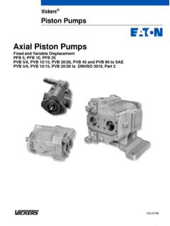
6 This accelerated motion is called Kinetic Energy , which is the energy in motion. The shape of the volute permits the liquid to expand, which slows down the motion of the liquid. As soon as the liquid slows down inside the volute, Kinetic Energy is transformed into pressure. This pressure then forces the liquid out of the pump discharge nozzle into the outlet pipe lines. 17. Nomenclature and Description 18. Nomenclature and Description Continued .. The diagram shows the main parts of the centrifugal pump. The impeller is fastened to the shaft. The shaft passes through the pump casing and out through the stuffing box (portion of the casing through which the shaft extends and where seal or packing is placed). In order to keep the liquid from leaking out of the casings between the stuffing box and the shaft, Packing or Mechanical Seal is used. The shaft is supported by two bearing housing and is then connected by a coupling installed between the pump shaft and the motor shaft.
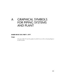
7 19. Nomenclature and Description Continued .. 20. Different Types of Impeller The impeller of a Centrifugal Pump can be of three types: Open Impeller: The vanes are cast free on both sides. Semi-Open Impeller: The vanes are free on one side and enclosed on the other. Enclosed Impeller: The vanes are located between the two discs, all in a single casting. 21. Centrifugal pump Curves- Characteristics Head and Capacity A rating curve indicates the relationship between the head (pressure) developed by the pump and the flow through the pump based on a particular speed and impeller diameter when handling a liquid. As the capacity increases, the total head which the pump is capable of developing decreases. In general, the highest head the Centrifugal Pump can develop is at the point where there is no flow through the pump. 22. Centrifugal pump Curves- Characteristics Continued.
8 BHP (Brake Horsepower) and Capacity For the Centrifugal pump to deliver the capacity we want, we must supply the pump with a certain HP. Generally, the HP increases as we increase the capacity. BHP: is the total power required by a pump to do a specified amount of work. BHP = Q x H x 3960 x Efficiency 23. Centrifugal pump Curves- Characteristics Continued .. Efficiencies Efficiency of a pump can be calculated by: Eff = Q x H x x 100. 3960 x HP. where, Eff = Efficiency (%). Q = Capacity delivered by the pump H = Head developed by the pump Sp. Gr = Specific Gravity of liquid being pumped HP = Horsepower required by the pump 24. Centrifugal pump Curves- Characteristics Continued .. 3960 is a constant linking a HP (33,000 ft lbs / min) to a US. GPM ( lbs). 33000 = 3960. 25. Centrifugal pump Curves- Characteristics Continued .. NPSH and Capacity The curve shows the relationship between the capacity which the pump will deliver and the NPSH (net positive suction head), which is required for proper operation of the pump at that capacity.
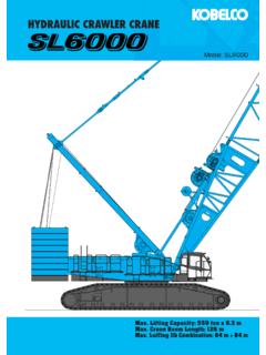
9 Lack of NPSH measured in Feet of the liquid pumping, will cause the pump to operate improperly and cause cavitations. 26. Centrifugal pump Curves- Characteristics Continued .. Overall Rating By plotting all the characteristics of a Centrifugal Pump on one coordinate system, we can define the capabilities and limitations of the pump. 27. Specific Speed Specific Speed is used to describe the geometry (shape) of a pump impeller. Performance of Centrifugal pump is expressed in terms of pump speed, total head and, required flow. Specific Speed is calculated using the formula below at pump's BEP. Formula: Specific Speed (Ns)= N Q. N: speed of pump (rpm), H (3/4). Q: flow, H: head 28. Specific Speed Continued .. 29. Centrifugal pump Curves- Characteristics Continued .. System Curves Pressure loss and Friction Loss Simple System with Point A and B on same level. Assume a line through which liquid is flowing and also assume heat exchangers, valves and other items which add to total friction loss.
10 Friction loss through the system will increase as we increase the capacity (velocity). Friction loss is proportional to the square of capacity. At zero flow, there is no friction loss. 30. Centrifugal pump Curves- Characteristics Continued .. Point B is higher than Point A. Necessary to add energy to the fluid to get to Point B from A. The amount of energy required is exactly equal to the difference in elevation between Point A and B, assuming friction loss as before. 31. Centrifugal pump Curves- Characteristics Continued .. Friction Curve will be the same in both systems because the friction loss is the same. We just added constant amount of head at any capacity to get the liquid from one point to another. 32. Centrifugal pump Curves- Characteristics Continued .. Assume pressure at Point A different than pressure at Point B. If we take suction at Point A from an open tank and discharge it at Point B in a closed tank, even though Point A and B are at the same level, we must still overcome the differential pressure between both points.