Transcription of Prosonic T FMU30 - fotonika.kiev.ua
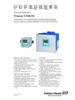
1 Technical Information Prosonic T FMU30 . ultrasonic level measurement Compact transmitters for non-contact level measurement of fluids, pastes and coarse bulk materials Application Features and benefits Continuous, non-contact level measurement in fluids, Quick and simple commissioning via menu-guided on- pastes, sullages and coarse bulk materials site operation with four-line plain text display System integration via 4 to 20mA Envelope curves on the on-site display for simple Maximum measuring range: diagnosis 1 " sensor: 5 m (16 ft) in fluids Linearisation function (up to 32 points) for conversion 2 m (6 ft) in bulk materials of the measured value into any unit of length, volume 2" sensor: 8 m (26 ft) in fluids or flow rate m (11 ft) in bulk materials Non-contact measurement method minimizes service requirements Installation possible from thread G 1 or 1 NPT. upwards Integrated temperature sensor for automatic correction of the temperature dependent sound velocity TI440F/00/ 71105940.
2 Prosonic T FMU30 . Inhaltsverzeichnis Function and system design.. 2 Housing design .. 16. Measuring principle .. 2 Process connection, sensor material, matching layer .. 16. Equipment architecture .. 4. Human interface .. 17. Input .. 5 Display and operating elements .. 17. Measured variable .. 5 On-site operation .. 19. Measuring range .. 5 Remote operation .. 19. Operating frequency .. 6. Certificates and Approvals .. 21. Output .. 7 CE mark .. 21. Output signal .. 7 Ex approval .. 21. Signal on alarm .. 7 External standards and guidelines .. 21. Output damping .. 7. Linearisation .. 7 Ordering information.. 22. FMU30 .. 22. Auxiliary energy .. 8 Scope of delivery .. 22. Terminal compartment .. 8. Terminal assignment .. 8 Accessories .. 23. Supply voltage .. 9 Installation bracket .. 23. Terminals .. 9 Screw in flange .. 23. Cable entry .. 9 Cantilever .. 25. Cable gland .. 9 Mounting Frame .. 26. Power consumption .. 9 Wall Bracket.
3 26. Current consumption .. 9 Commubox FXA291 .. 27. ToF Adapter FXA291 .. 27. Performance characteristics.. 10. Reaction time .. 10 Supplementary documentation .. 27. Reference operating conditions .. 10 Operating manual .. 27. Measured value resolution .. 10 Description of device functions .. 27. Pulse frequency .. 10 Short instructions .. 27. Measuring error .. 10. Influence of the vapor pressure .. 10. Installation conditions .. 11. Installation variants .. 11. Installation conditions for level measurements .. 12. Installation in narrow shafts .. 12. Installation conditions for flow measurements .. 13. Blocking distance, nozzle installation .. 14. Ambient conditions .. 15. Ambient temperature .. 15. Storage temperature .. 15. Resistance to alternating temperature cycles .. 15. Climate class .. 15. Ingress protection .. 15. Vibration resistance .. 15. Electromagnetic compatibility (EMC) .. 15. Process conditions .. 15. Process temperature.
4 15. Process pressure .. 15. Mechanical construction .. 16. Design; dimensions .. 16. Weight .. 16. 2 Endress+Hauser Prosonic T FMU30 . Function and system design Measuring principle BD. SD. 20 mA. 100%. D. E. F. L. 4 mA. 0%. L00- FMU30 -15-00-00-xx-001. E: Empty distance F: Span (full distance). D: Distance from sensor membrane - product surface L: Level BD: Blocking distance SD: Safety distance Sensor BD Max. range fluids Max. range bulk materials 1 " m ( ft) 5 m (16 ft) 2 m ( ft). 2" m ( ft) 8 m (26 ft) m (11 ft). Time-of-flight method The sensor of the instrument transmits ultrasonic pulses in the direction of the product surface. There, they are reflected back and received by the sensor. The instrument measures the time t between pulse transmission and reception. The instrument uses the time t (and the velocity of sound c) to calculate the distance D between the sensor membrane and the product surface: D = c t/2. As the device knows the empty distance E from a user entry, it can calculate the level as follows: L=E-D.
5 An integrated temperature sensor compensates for changes in the velocity of sound caused by temperature changes. Interference echo suppression The interference echo suppression feature on the instrument ensures that interference echos ( from edges, welded joints and installations) are not interpreted as a level echo. Calibration Enter the empty distance E and the span F to calibrate the device. Blocking distance Span F may not extend into the blocking distance BD. Level echos from the blocking distance cannot be evaluated due to the transient characteristics of the sensor. Endress+Hauser 3. Prosonic T FMU30 . Equipment architecture The complete measuring system consists of: PLC FieldCare Commubox FXA291 and ToF Adapter FXA291. operating and display module %. E. transmitter power supply unit RMA422 or RN221N. (communication resistor included). ENDRESS + HAUSER. RMA 422. FMU30 . L00-FMU30xxx-14-00-06-en-008. On-site operation with display and operating module with a PC, Commubox FXA291 + ToF Adapter FXA291 and the operating software FieldCare 4 Endress+Hauser Prosonic T FMU30 .
6 Input Measured variable The distance D between the sensor membrane and the product surface is measured, see also figure 3. Using the linearisation function, the device uses D to calculate: level L in any units volume V in any units flow Q across measuring weirs or open channels in any units Measuring range The measuring range is limited by the range of a sensor. The sensor range is, in turn, dependent on the operating conditions. To estimate the actual range, proceed as follows (see also the calculation example in the diagram): 1. Determine which of the influences shown in the following table are appropriate for your process. 2. Add the corresponding attenuation values. 3. From the total attenuation, use the diagram to calculate the range. Fluid surface Attenuation Calm 0 dB. Waves 5 to 10 dB. Strong turbulence ( stirrers) 10 to 20 dB. Foaming Ask Endress+Hauser Bulk material surface Attenuation Hard, rough ( rubble) 40 dB. Soft ( peat, dust-covered clinker) 40 to 60 dB.
7 Dust Attenuation No dust formation 0 dB. Little dust formation 5 dB. Heavy dust formation 5 to 20 dB. Filling curtain in detection range Attenuation None 0 dB. Small quantities 5 to 10 dB. Large quantities 10 to 40 dB. Temperature difference between Attenuation sensor and product surface to 20 C (68 F) 0 dB. to 40 C (104 F) 5 to 10 dB. to 60 C (140 F) 10 to 15 dB. Endress+Hauser 5. Prosonic T FMU30 . 10. range/ m Sensor 2". 5. Sensor 1 ". 1. 10 20 30 40 50 60 70 80. attenuation / dB. L00-FMU30xxx-05-00-00-en-002. Example strong turbulence surface approx. 20 dB. no dust formation 0 dB. Filling curtain in detection range 10 dB. Temperature diff. < 20 C 0 dB. approx. 30 dB => range approx. m (26 ft) for FMU30 2" sensor Operating frequency 1 " sensor 2" sensor approx. 70 kHz approx. 50 kHz 6 Endress+Hauser Prosonic T FMU30 . Output Output signal 4 to 20 mA. Signal on alarm Error information can be accessed via the following interfaces: On-site display (error symbol, error code and plain text description).
8 Current output (error current configurable). Output damping Freely selectable, 0 to 255 s Linearisation The linearisation function of the instrument allows conversion of the measured value into any unit of length or volume. In open channels or measuring weirs, also a flow linearistion is possible (calculation of the flow from the measured level). The linearisation table for calculating the volume in an horizontal cylindrical tank is preprogrammed. You can also enter any number of other tables containing up to 32 value pairs either manually or semi-automatically (by filling the vessel under controlled conditions). Endress+Hauser 7. Prosonic T FMU30 . Auxiliary energy Terminal compartment The terminals are located underneath the housing cover. A. B. Display 1 2. C. D. L00-FMU30xxx-04-00-00-xx-001. A: terminals B: optional: display C: internal earth terminal D: external earth terminal Terminal assignment power mA. plant 1 2 3 ground L- L+.
9 L00-FMU30xxx-04-00-00-en-015. Connect the connecting line to the screw terminals (line cross-sections of to ( to in)). in the terminal compartment. A standard installation cable is sufficient for the connection. Protective circuitry against reverse polarity, RFI and over-voltage peaks is built into the device (see also Technical Information TI241F/00/EN "EMC Test Procedures"). 8 Endress+Hauser Prosonic T FMU30 . Supply voltage The following values are the voltages across the terminals directly at the instrument: Current Terminal voltage Terminal voltage minimum consumption maximum 4 mA 14 V 35 V. 20 mA 8V 35 V. Terminals Cable cross-section: to mm2 (20 to 14 AWG). Cable entry G or NPT. Cable gland (recommended cable diameter 6 to 10 mm ( to in)). Power consumption 51 mW to 800 mW. Current consumption to 22 mA. Endress+Hauser 9. Prosonic T FMU30 . Performance characteristics Reaction time The reaction time depends on the parameter settings.
10 The minimum value is: min. 2 s Reference operating Temperature = +20 C (68 F). conditions Pressure = 1013 mbar abs. (15 psi abs.). Humidity = 50 %. Ideal reflective surface ( calm, smooth fluid surface). No interference reflections within signal beam Set application parameters: Tank shape = flat ceiling Medium property = liquid process conditions = calm surface Measured value resolution 1 mm ( in). Pulse frequency max. The exact values are dependent on the type of device and the parameter settings. Measuring error Typical specifications for reference operating conditions (include linearity, repeatability, and hysteresis): 3 mm ( in) or of set measuring distance (empty calibration)1. 1. whichever is greater Influence of the vapor The vapor pressure at 20 C (68 F) gives a hint on the accuracy of the ultrasonic level measurement . If the pressure vapor pressure at 20 C (68 F) is below 50 mbar (1 psi), ultrasonic level measurement is possible with a very high accuracy.
