Transcription of Technical Information Prosonic S FMU90 - …
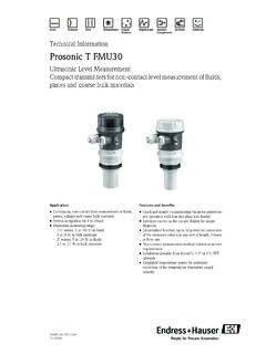
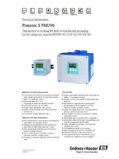
1 TI397F/00/ InformationProsonic S FMU90 Transmitter in housing for field or top-hat rail mountingfor the ultrasonic sensors FDU91/91F/92/93/95/96 Application for level measurement Continuous, non-contact level measurement of fluids, pastes, sludge and powdery to coarse bulk materials with 1 or 2 ultrasonic sensors Measuring range up to 70 m(depending on sensor and material measured) Level limit detection (up to 6 relays) Pump control (alternating) Screen and rake control Calculations: average, difference, sumApplication for flow measurement Flow measurement in open channels and measuring weirs with 1 or 2 ultrasonic sensors Simultaneous measurement of level and flow in a stormwater overflow basin with only 1 sensor Flow measurement with back water detection (2 sensors) or sludge detection Up to 3 (non-resettable) totalizers and 3 (resettable) counters configurable Counting or time pulse output for control of external unitsYour benefits Simple, menu-guided operation with 6-line plain text display Envelope curves on the display for quick and simple diagnosis Easy operation, diagnosis and measuring point documentation with the supplied "ToF-Tool - FieldTool Package" operating program.
2 Temperature dependent time-of-flight correction via the integrated temperature measurement in the sensors Linearisation (up to 32 points, freely configurable) Linearisation tables for the most common flumes and weirs pre-programmed and selectable Online calculation of the flume-/weir-flows via integrated flow curves System integration via HART or PROFIBUS DP Automatic detection of the sensors FDU91/91F/92/93/95/96 The sensors of the former series FDU8x can be connected (for certificates see note on page 8) adjustable to the individual requirements via product structureProsonic S FMU902 Endress + HauserTable of ContentsFunction and system design.. 3 Measuring principle .. 3 Blocking distance .. 3 Time-of-flight correction .. 3 Interference echo suppression .. 3 Pump control .. 3 Linearisation .. 4 Special functions .. 4 Datalog functions .. 4 Application examples for level measurements .. 5 Application examples for flow measurements .. 6 System integration HART.
3 7 System integrationPROFIBUS DP .. 7 Input .. 8 Sensor inputs .. 8 Output .. 9 Analogue outputs .. 9 Relay outputs .. 9 PROFIBUS DP interface .. 10 Auxiliary energy .. 10 Supply voltage/Power consumption/Current consumption .. 10 Galvanic isolation .. 10 Fuse .. 10 Electrical connection .. 11 Terminal compartment of the field housing .. 11 Cable entries of the field housing .. 11 Terminal compartment of the DIN-rail housing .. 12 Terminals .. 13 Terminal assignment .. 14 Connection of the sensors FDU9x .. 17 Synchronization line .. 18 Connection of the separate display and operating module .. 18 Performance characteristics.. 19 Reference operating conditions .. 19 Measuring uncertainty .. 19 Typical accuracy .. 19 Measured value resolution .. 19 Measuring frequency .. 19 Ambient conditions .. 19 Ambient temperature .. 19 Storage temperature .. 19 Climate class .. 19 Vibration resistance .. 19 Ingress protection .. 19 Electromagnetic compatibility (EMC).
4 20 Mechanical construction .. 20 Housing versions .. 20 Dimensions of the field housing .. 20 Dimensions of the DIN-rail housing .. 21 Dimensions of the separate display and operating module .. 23 Weight .. 23 Materials .. 23 Human interface .. 24 Display and operating module .. 24 Operating menu .. 24 Quick Setup .. 24 Locking of the instrument .. 24 Certificates and Approvals .. 25CE mark .. 25Ex approval .. 25 External standards and guidelines .. 25 Ordering Information .. 26 Product structure .. 26 Scope of delivery .. 26 Accessories .. 27 Commubox FXA191 HART .. 27 Commubox FXA195 HART .. 27 Commubox FXA291 IPC .. 27 Protection cover for the field housing .. 27 Mounting plate for the field housing .. 27 Mounting bracket .. 28 Adaption plate for remote display .. 28 Overvoltage protection HAW56x .. 29 Supplementary documentation .. 33 Innovation booklet .. 33 Technical Information .. 33 Operating instructions(for transmitter FMU90 ).
5 33 Description of Instrument Functions .. 33 Safety Instructions (XA) .. 33 Control Drawings (ZD) .. 33 Prosonic S FMU90 Endress + Hauser3 Function and system designMeasuring principleL00-FMU90xxx-15-00-08-xx-009BD: blocking distance; D: distance from sensor membrane to fluid surface; E: empty distance F: span (full distance);L: level; V: volume (or mass); Q: flowThe sensor transmits ultrasonic pulses in the direction of the product surface. There, they are reflected back and received by the sensor. The transmitter Prosonic S measures the time t between pulse transmission and reception. From t (and the velocity of sound c) it calculates the distance D from the sensor membrane to the product surface:D = c t/2 From D results the desired measuring value: level L volume V flow Q across measuring weirs or open channelsBlocking distanceThe span F may not extend into the blocking distance BD. Level echos from the blocking distance can not be evaluated due to the transient characteristics of the sensor.
6 The blocking distances of the individual sensors are given in the following documents: TI 396F for the sensors FDU 91/91F/92/93/95/96 TI 189F for the sensors FDU 80/80F/81/81F/82/83/84/85/86 Time-of-flight correctionIn order to compensate for temperature dependent time-of-flight changes, a temperature sensor is integrated in the ultrasonic echo suppressionThe interference echo suppression feature of the Prosonic S ensures that interference echos ( from edges, welded joints and installations) are not interpreted as a level controlindividaully configurable for each pump: pump switching delay, to prevent overlaod of the power supply system backlash time and backlash interval, for complete draining of shafts or channels crust reduction at pump shaft walls by fine adjustment of the switch pointFDU9xProsonic SFMU90 Prosonic SFMU90 FDU9xDQ100%0%DLFEBDVP rosonic S FMU904 Endress + HauserLinearisationPre-programmed linearisation curvesTypes of vessels horizontal, cylindrical tank spherical tank tank with pyramidal bottom tank with conical bottom tank with flat, inclined bottomFlow curves for flumes and weirs1) Khafagi-Venturi flume ISO-Venturi flume BST2)-Venturi flume Parshall flume Palmer-Bowlus flume Rectangular weir Rectangular constricted weir NFX3) rectangular weir NFX3 rectangular constricted weir Trapezoidal weir V-notch weir BST2 V-notch wier NFX3 V-notch weirThe pre-programmed linearisation curves are calculated formula for flow measurements1Q = C (h + h )"h" is the upstream level.
7 The parameters , , and C can be freely programmed by the tableconsisting of up to 32 linearisation points; to be entered manually or functions limit detection rake control alternating pump control or control according to pump rate totalising of the flow volume with (resettable) counters and (non-resettable) totalisers1 triggering of a sampler by time or quantity pulses1 low flow cut off1 backwater detection in flumes1 sludge detection in flumes1 trend detectionDatalog functionsBasic version Peak hold indicator of the levels or flows and the temperatures at the sensors Recording of the last 10 alarms Indication of the operating status Trend indication of the outputs on the on-site display Indication of the operating hours1) for instrument versions with flow software ( FMU90 - *2**)2) BST: British Standard3) French standard NFX 10-311 Prosonic S FMU90 Endress + Hauser5 Application examples for level measurementsLevel measurement with limit detection and alarm outputL00-FMU90xxx-15-00-00-xx-010 Order code.
8 FMU90 - *1**131**(1 input, 3 relays, 1 outputs)Average level measurementL00-FMU90xxx-15-00-00-xx-003 Order code : FMU90 - *1**212**(2 inputs, 2 outputs)minProsonic SmaxminLFDU9xLmaxProsonic SL1 + L22L1L2 Rake control(differential measurement )L00-FMU90xxx-15-00-00-xx-004 Order code : FMU90 - *1**212**(2 inputs, 1 relay, 2 outputs)Alternating pump control(up to 6 pumps)L00-FMU90xxx-15-00-00-xx-007 Order code : FMU90 - *1**131**(1 input, 3 relays) Prosonic SD1D2 MLProsonic SConveyor beltL00-FMU90xxx-15-00-00-xx-005 Order code : FMU90 - *1**111**(1 input, 1 output)DProsonic SProsonic S FMU906 Endress + HauserApplication examples for flow measurementsPulses for volume counter + time pulses ( for sampler)L00-FMU90xxx-15-00-00-xx-011 Order code : FMU90 - *2**131**(1 input, 3 relays, 1 output)Flow measurement with backwater alarm or sludge detectionIf the ratio "downstream level:upstream level" rises above or falls below a critical value, an alarm will be code : FMU90 - *2**212**(2 inputs, 1 relay, 2 outputs)FDU9xDQProsonic S123m3 QProsonic SStormwater overflow bassinSimultaneous measurement of level L and flow Q with 1 code : FMU90 - *2**112**(1 input, 2 outputs)LQ(l/s)L (m)Q (l/s) Prosonic S123m3 Prosonic S FMU90 Endress + Hauser7 System integration HARTL00-FMU90xxx-14-00-00-xx-009In the standard version a HART signal is superimposed onto the first output current.
9 In order to use the HART communication, the circuit must contain a communication resistor of 250 .Operating options via the operating and display module at the Prosonic S (if present) via the service interface of the Prosonic S with the Commubox FXA291 and the operating program "ToF Tool - FieldTool Package" or "FieldCare" via the HART protocol, with the Commubox FXA191 or FXA195 and the operating program "ToF Tool - FieldTool Package" or "FieldCare" via the HART handheld terminal DXR375 System integrationPROFIBUS DPL00-FMU90xxx-14-00-00-xx-010 Operating options via the display and operating module at the Prosonic S via the service interface with the Commubox FXA291 and the operating program "ToF Tool - FieldTool Package" or "FieldCare" via PROFIBUS DP with Profiboard or Proficard and the operating program "ToF Fool - FieldTool Package" or "FieldCare"DXR375 SPS / PLC / APIC ommuboxFXA191 (RS232)FXA195 (USB)ToF ToolFieldToolPackage1# % &CopyG H IP Q R S, ( ) A B CPastePageOnPageUpDeleteBkspInsertJ K LT U V_ < >D E FHot Key+ Hot KeyM N OW X Y Z+ * COMMUNICATOR369-DELTABAR: * * * * * * * *ONLINE1 QUICK SETUP2 OPERATING MENU4 SV0 C3 PV352 mbarHELPSAVE dsdmdmdf faasas # % &CopyG H IP Q R S, ( ) A B CPastePageOnPageUpDeleteBkspInsertJ K LT U V_ < >D E FHot Key+ Hot KeyM N OW X Y Z+ * COMMUNICATOR369-DELTABAR: * * * * * * * *ONLINE1 QUICK SETUP2 OPERATING MENU4 SV0 C3 PV352 mbarHELPSAVE dsdmdmdf faasas ToolFieldToolPackageProsonic SCommuboxFXA 291 FieldCareFieldCareI : 4.
10 20 mA + HART1 PROFIBUS DPToF ToolFieldToolPackageSPS / PLC / APIP rosonic SProfiboardProficardToF ToolFieldToolPackageCommuboxFXA 291 FieldCareFieldCareProsonic S FMU908 Endress + HauserInputSensor inputsDepending on the instrument version, 1 or 2 of the sensors FDU91, FDU92, FDU93, FDU95 and FDU96 can be connected. The Prosonic S identifies these sensors order to support existing installations, the sensors of the former series FDU8x can be connected as well. The type of sensor must be entered manually.#Warning! The sensors FDU83, FDU84, FDU85 and FDU86 with an ATEX, FM or CSA certificate are not certified for connection to the transmitter range1) in liquids1) This table gives the maximum range. The range depends on the measuring conditions. For an estimation see Technical Information TI 396F, chapter "Input".10 m20 m25 m--max. range1 in solids5 m10 m15 m45 m70 mSensorFDU80 FDU80 FFDU81 FDU81 FFDU82 FDU83 FDU84 FDU85 FDU86max. range1) in liquids1) This table gives the maximum range.