Transcription of PTAC Packaged Terminal Air Conditioners & Heat Pumps ...
1 Installation and Operation ManualPTACP ackaged Terminal AirConditioners & heat Pumps9830 1000_00 (01/15)SG SERIES2 Table of ContentsCongratulations ..3 General Instructions ..3 General Specifications ..4 Installation Checklist ..4 PTAC Installation Recommendations ..5 Wall Sleeve Installation Instructions (PDXWS) ..6 Alternate Wall Installations ..7 One-Piece Deep Wall Sleeve Installation (PDXWSEXT) ..9 PXDR10 Drain Kit Installation Instructions (optional for new construction) ..10 External Drain (for new construction or unit replacement) ..11 PXGA Standard Grille Installation Instructions ..12 Electrical Wiring for 265 Volt Models ..14 Chassis Install Preparation.
2 16 Chassis Installation ..18 How To Connect ..19 Friedrich PTAC Digital Control and Unit Features ..20 System Configuration ..22 Digital Control User Input Configuration ..23 Digital Control Operation ..24 Remote Control Thermostat Installation ..25 Remote Thermostat and Low Voltage Control Connections ..25 Final Inspection & Start-up Maintenance ..27 Basic Troubleshooting ..28 Service & Assistance ..29 Accessories ..30 NOTE: All PTAC 7000, 9000, 12000 units come with a standard kW power cord. All PTAC 15000 units come with a standard 5 kW power cord For units using our optional heating cords ( kW, kW, and 5 kW) please refer to page 14 for the proper accessory part numbers and power cord installation instructions.
3 3 CongratulationsThank you for your decision to purchase Friedrich. Your new Friedrich has been carefully engineered and manufactured to give you many years of dependable, efficient operation, maintaining a comfortable temperature and humidity level. Many extra features have been built into your unit to assure quiet operation, the greatest circulation of cool, dry air, and the most economic InstructionsThis Installation and Operation Manual has been designed to insure maximum satisfaction in the performance of your unit. For years of trouble-free service, please follow the installation instructions closely. We cannot overemphasize the importance of proper are some suggestions to help you use your new Friedrich most efficiently:1.
4 Carefully read and follow the installation Make sure the unit is the right capacity for the area being cooled. An undersized unit makes the unit work too hard, using more electricity than needed and increases wear. An oversized unit will cycle on and off too rapidly, and therefore cannot control humidity as Clean the filter frequently (See Routine Maintenance, Page 27).4. Do not block the air flow to and from the A dirty filter or improperly set controls can affect the cooling ability of the If cooling is weak and you have verified that the filter is clean and the controls are properly set, the unit may need service and you should call your Friedrich service provider to check the Keep blinds, shades and drapes closed on the sunny side of the room being cooled to reduce radiant Proper insulation helps your unit maintain the desired inside Whenever possible, shade south and west facing Keep window coverings away from the unit to provide free air systemunder high pressureDo not puncture, heat .
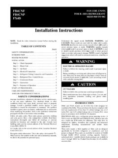
5 Expose to flame certified refrigeration technicians shouldservice this use gauge sets designed for use withR410A. Do not use standard R22 gauge systems operate at higher pressuresthan R22 equipment. Appropriate safeservice and handling practices must be Installation OperationManualPlease read this manual thoroughly prior toequipment installation or is the installer s responsibility to properlyapply and install the equipment. Installationmust be in conformance with the NFPA 70-2008 National Electric Code or current edition,International Mechanic Code 2009 or currentedition and any other applicable local ornational to do so can result in property damage,personal injury or safety and the safety of others are very have provided many important safety messages in this manual and on your appliance.
6 Always read and obey all safety is a safety Alert symbol alerts you to potential hazards that can kill or hurt you and safety messages will follow the safety alert symbol with the word WARNING or CAUTION . These words mean:Indicates a hazard which, if not avoided, can result in severe personal injury ordeath and damage to product or other a hazard which, if not avoided, can result in personal injury anddamage to product or other safety messages will tell you what the potential hazard is, tell you how to reduce the chance of injury, and tell you what will happen if the instructions are not property damage can occur if instructions are not SpecificationsInstallation Checklistq Inspect all components and accessories for damage before and after Remove the cardboard wall sleeve support and grill Check for proper wall sleeve installation in accordance with the wall sleeve installation Check for a subbase kit or other means of structural support which is required for ALL installations projecting more than 8" into Install the recommended Condensate Drain Kits for complete condensate Ensure that the chassis is installed in a 16" high x 42 wide wall sleeve that is no
7 Deeper than 13 ". A baffle kit is required if the sleeve exceeds that Ensure that chassis and chassis front cover are installed and secured Ensure that drapes, bed, bedspread, furniture, etc. DO NOT block either return or discharge air Inspect the condenser air inlet and outlet for any obstructions (shrubbery, etc.)q Ensure that 'reset' button is pressed on LCD device (only on cord connected models).MODEL NUMBER07=7,000 Btuh09=9,000 BtuhNominal Capacity12=12,000 Btuh15=15,000 BtuhSeriesPD =FriedrichDigitalPTACS ystemE=CoolingwithorwithoutelectricheatH =HeatPumpwithAuxiliaryHeatVoltageK=230/2 08V - 1Ph. - - 1Ph. - (230 Vor265V) 2 = KW 3 = KW 5 = KW** kw only available on 9,000 12,000 and 15,000 BTU modelsChassisS=StandardDesignSeriesEngin eeringDigitPDNote: All PTAC models with a C design series or later come standard with Diamonblue seacost protection and digital = AccessoryE5 PTAC Installation RecommendationsPTAC units should be installed no closer than 12" apart when two units are side by side.
8 If three or more PTAC units are to operate next to one another allow a minimum of 36" between units. Also, a vertical clearance of 60" should be maintained between units installed. In the interior of the room the unit should be located a minimum of 1/4" from the floor and a minimum of 36" from the ceiling. For minor obstructions such as lamp poles or small shrubbery a clearance of 12" from the outdoor louver should be maintained. For major obstructions such as a solid fence, wall or other heat rejecting device like a condensing unit, a minimum distance of 36" should be proper PTAC unit performance and maximum operating life refer to the minimum installation clear-ances below:For PTACs on the ground floor or anytime obstructions are present, use the following guidelines:The above suggestions are for reference only and do not represent all possible installations.
9 Please contact Friedrich for information regarding affects of other installation arrangements. By following these simple recommendations you can be confident that your Friedrich PTAC will provide years of worry free 1 Figure 2 FRP002 PTACSHRUBPOLEFENCE OR WALLCATPCATPTYPICAL BUILDING ( PLAN VIEW )CONDENSING UNIT12"36"36"36"36" MIMUMUM, MAJOROBSTRUCTIONS12" MINIMUM, MINOROBSTRUCTIONSFRP001 THREE OR MORE PTACsADJACENT 36" MINIMUMGROUND FLOOR PTACs6" MINIMUM FROM GRADETWO ADJACENT PTACs12" MINIMUMTYPICALWINDOWVIEW: OUTSIDE BUILDING ELEVATION60" VERTICALMIMUMUMBETWEENPTACs12"6"36"60"6 Wall Sleeve Installation Instructions (PDXWS)NOTE: Insure that the unit is only installed in a wall structurally adequate to support the unit including the sleeve, chassis and accessories.
10 If the sleeve projects more than 8" into the room, a subbase or other means of support MUST be used. Please read these instructions completely before attempting Deep Wall Installation (Greater than 13 1/4") See Page 9 The following instructions apply ONLY to walls less than 13 " in depth. 1. The PXDR10 Drain Kit (optional for new construction) see page 10 if applicable, must be installed before the wall sleeve is installed into the The External Drain (for new construction or unit replacement) see page 11, if applicable, must be installed before the wall sleeve is installed into the From inside the building, position the wall sleeve in the opening and push it into the wall until it protrudes at least on the outside.