Transcription of QS Link Power Supply SPEC (369886) - Lutron Electronics …
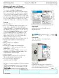
1 SPECIFICATION SUBMITTALPageJob Name:Job Number:Model Numbers:QS SystemQS Supply369886f 1 , WQSPS-DH-1-75L(+)N(-)100 - 277 VInput / Entrada / Entr e24 VOutput / Salida / - 25 VQSPS-DH-1-75, WQSPS-DH-1-75QS Link Power SupplyThe (W)QSPS-DH-1-75 QS link Power Supply provides up to 75 Power Draw Units (PDUs) on a QS link. The (W)QSPS-DH-1-75 powers additional compatible accessories and devices, allowing them to be added to a QS Numbers QSPS-DH-1-75 WQSPS-DH-1-75 (TAA Compliant)Input Power Nominal input voltage: 100 277 V~ Frequency: 50/60 Hz Current consumption, fully loaded (typical): A (277 V~) A (230 V~) A (120 V~) A (100 V~) Power Supply Output Nominal output voltage and tolerance: 24 V- / 1%, 75 Power Draw Units (PDUs)* A SELV / PELV / NEC Class 2 Power Draw Units (PDUs): Supplies 75 PDUs maximum* Note: This Power Supply is NOT rated for use with motorized shades/window Ambient operating temperature : 32 F to 131 F (0 C to 55 C).
2 Ambient operating humidity: 0% to 90% humidity, non-condensing. Indoor use only. Unit generates heat, maximum 28 BTU / hr 60 C maximum calibration point temperature. For more information, see Mount using in (35 mm) DIN rail in accordance with EN 60715 Dimensions in (90 mm) in (90 mm) in (61 mm)QSPS-DH-1-75 Regulatory Approvals UL cUL CE compliant NOM compliantWQSPS-DH-1-75 Regulatory Approvals ULEfficiency Meets the Department of Energy level VI efficiency standardWarranty * Use above this maximum will reduce the lifetime of the Supply and void all Lutron warranties. For more information about Power Draw Units (PDUs), please refer to SUBMITTALPageJob Name:Job Number:Model Numbers:QS SystemQSPS-DH-1-75, WQSPS-DH-1-75QS Supply369886f 2 shown as: in (mm)Mounting Surface mount using screws, or mount on DIN rail Use an IP20 (minimum) rated consumer panel or breaker panel with integrated DIN The device must be mounted horizontally ( connection terminal blocks on top).
3 DIN Rail Mounting:Snap onto DIN remove, pull out tabs with screwdriver and lift Mounting:Pull out tabs with through tabs to CONTACT8L(+)N( )100 277 VInput / Entrada / Entr e24 VOutput / Salida / 25 V103298_en_02 PHOENIX CONTACT8L(+)N( )100 277 VInput / Entrada / Entr e24 VOutput / Salida / 25 V* Required clearance above and below the Power (90) (150) (30)* (90) (30)* (61) (44) (50) (55)SPECIFICATION SUBMITTALPageJob Name:Job Number:Model Numbers:QS SystemQSPS-DH-1-75, WQSPS-DH-1-75QS Supply369886f 3 (+)N(-)100 - 277 VInput / Entrada / Entr e24 VOutput / Salida / - 25 VWiring Wire in accordance with national and local electrical codes Each terminal accepts one 24 AWG to 12 AWG ( mm2 to mm2) wire, with 1/4 in ( mm) stripped bare Maximum torque: in-lb to in-lb ( N m to N m)Line / Hot (L) and Neutral (N) from distribution panel+ 24 V- to terminal 2 of devices on the QS link.
4 Do not connect to terminal 2 of other Power sources on the QS link Common to terminal 1 of all devices on the QS link, including other Power sourcesL N++ QS Link Wiring LengthWire GaugeLutron Cable Part NumberLess than 500 ft (153 m) Power (terminals 1 and 2)1 pair 18 AWG ( mm2)GRX-CBL-346S (non-plenum)GRX-PCBL-346S (plenum)Data (terminals 3 and 4)1 twisted, shielded pair 22 AWG ( mm2)Up to 2000 ft (610 m) Power (terminals 1 and 2)1 pair 12 AWG ( mm2)GRX-CBL-46L (non-plenum)GRX-PCBL-46L (plenum)Data (terminals 3 and 4)1 twisted, shielded pair 22 AWG ( mm2) Output voltage adjustment knob (factory preset to 24 V- further adjustment not required) SPECIFICATION SUBMITTALPageJob Name:Job Number:Model Numbers:QS SystemQS Supply369886f 4 , WQSPS-DH-1-75QS Link Power DistributionOn the QS link, there are devices that Supply Power and devices that consume Power . Each device has a specific number of Power Draw Units (PDUs) it either supplies or consumes.
5 A Power Group consists of one device that supplies Power and one or more devices that consume Power ; each Power Group may have only one Power -supplying device. Refer to the Power Draw Units (PDUs) on the QS Link Specification Submittal ( Lutron P/N 369405) at for more information regarding Power Groups on the QS link, connect all 4 terminals (1, 2, 3, and 4), shown by the letter A in the diagram. Between devices on the QS link that Supply Power , connect only terminals 1, 3, and 4 (NOT terminal 2), shown by the letter B on the diagram. See Wiring section on the previous page for details on wiring the (W)QSPS-DH-1-75 Power Supply to the QS (+)N( )120 277 VInput / Entrada / Entr e24 VOutput / Salida / 25 VLUTRONGRAFIK Eye QS Control UnitEnergi Savr Node QS UnitQSE-CI-NWK-EQSE-IOseeTouch QS KeypadseeTouch QS KeypadseeTouch QS KeypadseeTouch QS KeypadseeTouch QS KeypadseeTouch QS KeypadQS Sensor Module and Occupancy SensorPower Group 1 Power Group 2 Power Group 3 Example: Power Group WiringQS Power Supply Power Group Wiring DetailBetween Power supplying devices: Connect only terminal 1 (common; terminal on the (W)QSPS-DH-1-75).
6 See previous Power Group 3 devices and (W)QSPS-DH-1-75: Connect terminals 1 (common) and 2 ( Power ).Between Power Group 3 devices powered by the (W)QSPS-DH-1-75, and other Power group devices: Connect terminals 1, 3 and 4 (communication/data).AAABBB Terminals 1, 2, 3, and 4 connect devices within a Power group. Terminals 1, 3, and 4 connect between Power Groups. terminal 2 is NOT connected between Power +1 3 4 QSPS-DH-1-75 Power Consuming DeviceQSPS-DH-1-75 SPECIFICATION SUBMITTALPageJob Name:Job Number:Model Numbers:QS SystemQSPS-DH-1-75, WQSPS-DH-1-75QS Supply369886f 5 Supply Breaker Feed(W)QSPS-DH-1-75 Power supplies have a large capacitive inrush when first powered. A dedicated breaker feed with no more than the indicated number of Power supplies is required to avoid nuisance Size/TypeMax (W)QSPS-DH-1-75 Units100 V~ to 127 V~15 A QO series standard trip curve 1320 A QO series standard trip curve 15220 V~ to 277 V~10 A (B trip curve) 210 A (C trip curve) 310 A (D trip curve) 616 A (B trip curve) 316 A (C trip curve) 516 A (D trip curve) 10 The Lutron logo, Lutron , GRAFIK Eye, Energi Savr Node, and seeTouch are trademarks or registered trademarks of Lutron Electronics Co.
7 , Inc. in the US and/or other countries. All other product names, logos, and brands are property of their respective owners.