Transcription of QSE-IO Control Interface (369374) - Lutron …
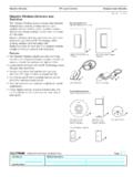
1 RSPECIFICATION SUBMITTALPageJob Name:Job number : model Numbers:QS SystemQSE-IOControl Interface369374d 1 Control InterfaceThe QSE-IO contact closure Interface provides integration with third-party equipment requiring contact closure input / output, including occupancy and vacancy sensors; motorized projection screens, skylights, and window shades; AV equipment; security systems; movable partition walls; and timeclocks. One QSE-IO Interface provides five (5) dry contact closure outputs and five (5) complete functionality, programming instructions, and detailed DIP switch settings, see the QSE-IO Programming Guide, Integrates a QS Control system with equipment that has contact-closure inputs and outputs. Provides five inputs and five dry contact closure outputs. Provides both normally open (NO) and normally closed (NC) contacts.
2 May be programmed to Control or be controlled on a QS - 36 V- 100 mASELV / PELV / NEC Class + + 7 6 5 4 3 2 1 PGMCCO 5 CCO 4 CCO 3 CCO 2 CCO 1 Status027557 61323 14321 COMV+MUXMUXQSCCO 1 NCCCO 1 NOCCO 2 NCCCO 2 NO1-2 COMCCO 3 NCCCO 4 NOCCO 3 NOCCO 4 NC3-4 COMCCO 5 NC5 COMCCO 5 NOCCI 1 CCI 2 CCI 3 CCI 4 COMCCI 5 VRV0-36 V-0-36 V~ AR1 AONQSE-IO Contact Closure Interface RSPECIFICATION SUBMITTALPageJob Name:Job number : model Numbers:QS SystemQSE-IOControl Interface369374d 2 Approvals UL Listed cUL Listed CE compliantPower SELV / PELV / NEC Class 2 Operating voltage: 24 36 V- 100 mAQS Link Limits The QS wired communications link is limited to 100 devices and 100 zones. Each QSE-IO Control Interface counts as 1 device and 5 zones. Each QSE-IO Control Interface consumes 3 Power Draw Units (PDU) on the QS link.
3 Refer to the QS Link Power Draw Units Specification Submittal (P/N 369405) at for more information. The maximum wiring length for the QS link is 2000 ft (610 m).Environment 32 F to 104 F (0 C to 40 C). Relative humidity less than 90% non-condensing. Indoor use only. Unit generates heat, maximum 8 BTU / and Operating Modes Using the inputs, contact closures in other equipment can operate Control units to: Select scenes Adjust scenes to reflect status of movable walls Toggle any combination of zones in the system between Off and a configurable preset value Turn lights on or off and / or move shades based on room occupancy Perform special functions such as sequencing, panic, Control lockout, or timeclock disable Using the outputs, scene and / or zone changes in Control units can: Trigger outputs to Control other equipment Provide status feedback to other equipmentFunctionality and Operating Modes (continued) Using the inputs, contact closures in other equipment can operate Sivoia QS window treatments to.
4 Open or close. Raise, lower, or stop. Select one of three adjustable presets. Using the outputs, key presses on QS window treatment keypads or GRAFIK Eye QS window treatment buttons can: Trigger outputs to other motorized window treatment equipment Scene selection Occupancy sensor Zone toggle Shade input Special functions Shade output Partitioning For a full list of functionality and operating modes, please see the Operating Modes and Dipswitch Settings table on Pages 8 and 9 Requirements QS Link Power Supply, such as a: - GRAFIK Eye QS - QS Link power supply, such as the QSPS-P1-1-50 - Energi Savr NodeTM QS - Quantum light management hub QS Communication Link (SELV / PELV/NEC Class 2) (see QS Link Wire Sizes table)RSPECIFICATION SUBMITTALPageJob Name:Job number : model Numbers.
5 QS SystemQSE-IOControl Interface369374d 3 Voltage0 24 V-0 24 V~Resistive AROutput Ratings+-24 LoadFlyback Diode (required for inductive loads) QSE-IO OutputNONCS pecifications (continued)Five Input Terminals Accept maintained inputs and momentary inputs with 40 msec minimum pulse times Off-state leakage current must be less than 100 A Open circuit voltage: 24 V- maximum Inputs must be dry contact closure, solid state, open collector, or active-low (NPN) / active high (PNP) output Open collector NPN or active-low on-state voltage must be less than 2 V- and sink mA Open collector PNP or active-high on-state voltage must be greater than 12 V- and source mAFive Output Terminals Provide selectable maintained or momentary (1/4 second) outputs (SELV / PELV / NEC Class 2 rated only) The QSE-IO is not rated to Control unclamped, inductive loads.
6 Inductive loads include, but are not limited to, relays, solenoids, and motors. To Control these types of equipment, a flyback diode must be used (DC voltages only). See "Terminal Locations" Output relays are non-latching (if relays are closed and power is lost, relays will open)Status LEDs Five Status LEDs light when associated output is active (on)RSPECIFICATION SUBMITTALPageJob Name:Job number : model Numbers:QS SystemQSE-IOControl Interface369374d 4 are in inches (mm) (63) (95) (108) (134) (27)Mounting holesTerminal blocks on this sideLEDs and addressing switches on this (9) (5) (5) (6)#6 or #8 (M3 or M4) screw recommendedMounting Hole DetailMounting OptionsMounting MethodsLUT-19AV-1U2 LUT-5x10-ENCC ontrol InterfaceWall13 Mount where terminal blocks, switches, and LEDs are accessible.
7 Strip 3/8 in (10 mm) of insulation from wires. Each data link terminal will accept up to two 18 AWG ( mm2) wires. Connect wiring as shown on the Wiring page. LED 1 lights continuously (Power) and LED 7 blinks rapidly (Data Link RX) when the SELV / PELV / NEC Class 2 Data Link is installed correctly. Choose from the following mounting methods:1 Direct Wall Mounting Mount the Control Interface directly on a wall, as shown in Mounting Methods at right, using screws (not included). When mounting, provide sufficient space for connecting Rack Mounting Place the unit in the LUT-19AV-1U AV rack using screws provided with the unit. The LUT-19AV-1U will hold up to four Enclosed Wall Mounting If conduit is desired for wiring, use the LUT-5x10-ENC to mount one SUBMITTALPageJob Name:Job number : model Numbers:QS SystemQSE-IOControl Interface369374d 5 r m i n a l L o c a t i o n s4321 Relay 1 NCRelay 1 NORelay 1 & 2 CommonRelay 2 NCRelay 2 NORelay 3 NCRelay 3 NORelay 3 & 4 CommonRelay 4 NCRelay 4 NORelay 5 NCRelay 5 NORelay 5 CommonInput 1 Input 2 Input 3 Input 4 Input 5 CommonCCI and CCO terminals each hold one 28 to 16 AWG ( to mm2) wireQS Data Link (to Control units, processor, and wallstations) 1: Common 2: V+ 3: MUX4.
8 MUXCCO 1 NCCCO 1 NO1-2 COMCCO 2 NCCCO 2 NOCCO 3 NCCCO 3 NO3-4 COMCCO 4 NCCCO 4 NOCCO 5 NCCCO 5 NO5 COMCCI 1 CCI 2 CCI 3 CCI 4 CCI 5 COMQSE-IOProgram Button1234567 DIP switchesLED 1: CCO 1 LED 2: CCO 2 LED 3: CCO 3 LED 4: CCO 4 LED 5: CCO 5 LED 6: UnusedLED 7: StatusNote: CCO LED is ON when CCO NO (normally open contact) is closed.}Contact Closure OutputsContact Closure InputsLED and DIP Switch LocationsQS Link Wire Sizes (check compatibility in your area)QS Link Wiring LengthWire GaugeLutronR Cable Part number < 500 ft (153 m)Power (terminals 1 and 2)1 pair 18 AWG ( mm2)GRX-CBL-346S (non-plenum)GRX-PCBL-346S (plenum)Data (terminals 3 and 4)1 twisted, shielded pair 22 AWG ( mm2)500 to 2000 ft(153 to 610 m)Power (terminals 1 and 2)1 pair 12 AWG ( mm2)GRX-CBL-46L (non-plenum)GRX-PCBL-46L (plenum)Data (terminals 3 and 4)1 twisted, shielded pair 22 AWG ( mm2)RSPECIFICATION SUBMITTALPageJob Name:Job number : model Numbers.
9 QS SystemQSE-IOControl Interface369374d 6 QS Link Wiring Methods (choose one)Powered by GRAFIK Eye QS Control UnitPowered by a QS Link Power Supply123412 ABC123456 LNTo additional wallstations/ Control interfacesTo additional wallstations/ Control interfacesRear View of GRAFIK Eye QS Control Unit Rear View of GRAFIK Eye QS Control Unit QS LinkQS LinkQS Link1: Common2: V+3: MUX4: MUXData Link:4: MUX3: MUXSee QS Link Wire Sizes table previous pageSELV / PELV/NEC Class 2 Power wiring: 2: V+ 1: CommonSee QS Link Wire Sizes table previous page System communication uses SELV / PELV/NEC Class 2 wiring. Follow all local and national electrical codes when installing SELV / PELV/NEC Class 2 wiring with line voltage / mains wiring. Each terminal accepts up to two 18 AWG ( mm ) wires.
10 Total length of Control link must not exceed 2000 ft (610 m). Typical Wire Sizes: See QS Link Wire Sizes table, previous page. Connect the terminal 1, 3, and 4 connections to all Control units, wallstations, and Control interfaces in the QS system. For terminal 2 connectivity, please refer to the wiring diagrams Cable See QS Link Wire Sizes table previous pageQS Power SupplyTo power source(1) 18 AWG ( mm2) Common(1) twisted pair22 AWG( mm2)RSPECIFICATION SUBMITTALPageJob Name:Job number : model Numbers:QS SystemQSE-IOControl Interface369374d 7 Application Examples1 LutronR Occupancy Sensor Wired to 1 QSE-IO Device InputQSE-IO TerminalsOccupancy Sensor (Wiring diagram is not applicable to: -500R, -1000R, or -2000R models)Power Pack(use model that corresponds to input voltage)HotNeutralRed (+20 to 24 V-)Blue (signal)Black (common)Blue (signal)Black (common)BlackWhiteRedRed120 / 277 / 347 V~ 60 Hz230 V~ 50 / 60 HzCCI1 CCI2 CCI3 CCI4 CCI5 COMP ower Pack(use model that corresponds to input voltage)Blue (signal)Black (common)3 LutronR Occupancy Sensors Wired to 1 QSE-IO Device InputQSE-IO TerminalsHotNeutralRed (+20 to 24 V-)Blue (signal)Black (common)BlackWhiteRedRed120 / 277 / 347 V~ 60 Hz230 V~ 50 / 60 HzCCI1 CCI2 CCI3 CCI4 CCI5 COMO ccupancy Sensors (Wiring diagram is not applicable to: -500R, -1000R, or -2000R models)NOTE.