Transcription of Qucs - A Tutorial
1 QucsA TutorialModelling Operational AmplifiersMike BrinsonCopyrightc 2006, 2007 Mike is granted to copy, distribute and/or modify this document under theterms of the GNU Free Documentation License, Version or any later versionpublished by the Free Software Foundation. A copy of the license is included inthe section entitled GNU Free Documentation License .IntroductionOperation amplifiers (OP AMP) are a fundamental building block of linear elec-tronics. They have been widely employed in linear circuit design since they werefirst introduced over thirty years ago. The use of operational amplifier models forcircuit simulation using SPICE and other popular circuit simulators is widespread,and many manufacturers provide models for their devices.
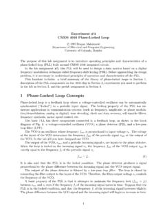
2 In most cases, thesemodels do not attempt to simulate the internal circuitry at device level, but usemacromodelling to represent amplifier behaviour as observed at the terminals of adevice. The purpose of this Tutorial note is to explain how macromodels can beused to simulate a range of the operational amplifier properties and to show howmacromodel parameters can be obtained from manufacturers data sheets. Thistutorial concentrates on models that can be simulated using qucs release qucs built-in operational amplifier modelQucs includes a model for an ideal operational amplifier. It s symbol can be foundin the nonlinear components list.
3 This model represents an operational amplifieras an ideal device with differential gain and output voltage limiting. The model isintended for use as a simple gain block and should not be used in circuit simulationswhere operational amplifier properties are crucial to overall circuit 1 shows a basic inverting amplifier with a gain of ten, based on the qucs OPAMP model. The simulated AC performance of this circuit is shown in Fig. Fig. 2 it is observed that the circuit gain and phase shift are constant anddo not change as the frequency of the input signal is increased. This, of course,is an ideal situation which practical operational amplifiers do not reproduce.
4 Letus compare the performance of the same circuit with the operational amplifierrepresented by a device level circuit. Shown in Fig. 3 is a transistor circuit diagramfor the well known UA741 operational amplifier1. The gain and phase results forthe circuit shown in Fig. 1, where the OP AMP is modelled by the UA741 transistorlevel model, are given in Fig. 4. The curves in this figure clearly illustrate thedifferences between the two simulation models. When simulating circuits thatinclude operational amplifiers the quality of the OP AMP model can often bea limiting factor in the accuracy of the overall simulation results.
5 Accurate OPAMP models normally include a range of the following device characteristics: (1)1 The UA741 operational amplifier is one of the most studied devices. It is almost unique inthat a transistor level model has been constructed for the device. Details of the circuit operationand modelling of this device can be found in (1) Paul R. Grey et. al., Analysis and Designof Analog Integrated Circuits, Fourth Edition, 2001, John Wiley and Sons INC., ISBN 0-471-32168-0, and (2) Andrei Vladimirescu, The SPICE book, 1994, John Wiley and Sons, simulationDC1ac simulationAC1 Type=logStart=1 HzStop=100 MHzPoints=801V1U=1 VOP1G=1e6 EquationEqn1d1=dB( )d2=phase( )R3R=47 kR4R= kVoutVinFigure 1: qucs schematic for a basic OP AMP inverting amplifier.
6 qucs OP AMPhas G=1e6 and Umax= and AC differential gain, (2) input bias current, (3) input current and voltageoffsets, (4) input impedance, (5) common mode effects, (6) slew rate effects, (7)output impedance, (8) power supply rejection effects, (9) noise, (10) output voltagelimiting, (11) output current limiting and (12) signal overload recovery effects. Theexact mix of selected properties largely depends on the purpose for which the modelis being used; for example, if a model is only required for small signal AC transferfunction simulation then including the output voltage limiting section of an OPAMP model is not necessary or indeed may be considered inappropriate.
7 In thefollowing sections of this Tutorial article macromodels for a number of the OP AMPparameters listed above are developed and in each case the necessary techniquesare outlined showing how to derive macromodel parameters from manufacturersdata HzdB( )1101001e31e41e51e61e71e80200400 Frequency Hzphase( ) DegreesFigure 2: Gain and phase curves for a basic OP AMP inverting 3: Transistor level circuit for the UA741 operational HzdB( )1101001e31e41e51e61e70100200 Frequency Hzphas( )Figure 4: Gain and phase curves for a times 10 inverting amplifier with the OPAMP represented by a transistor level UA741 OhmC1C= VR3R= OhmR2R=47k Ohmdc simulationDC1OP1G=1ac simulationAC1 Type=linStart=1 HzStop=10 MHzPoints=1800 SRC1G=1 ST=0 EquationEqn1d2=phase( )d1=dB( )VinVoutFigure 5: Modified qucs OP AMP model to include single pole frequency HzdB( )1101001e31e41e51e61e70510 Frequency Hzphase( ) DegreesFigure 6: Gain and phase curves for the circuit shown in Fig.
8 Features to the qucs OP AMP modelIn the previous section it was shown that the qucs OP AMP model had a frequencyresponse that is independent of frequency. By adding external components to theQucs OP AMP model the functionality of the model can be improved. The UA741differential open loop gain has a pole at roughly 5Hz and a frequency responsethat decreases at 20 dB per frequency decade from the first pole frequency up toa second pole frequency at roughly 3 MHz. The circuit shown in Fig. 5 modelsthe differential frequency characteristics of a UA741 from DC to around 1 6 illustrates the closed loop frequency response for the modified qucs OPAMP operational amplifier macromodelsMacromodelling is a term given to the process of modelling an electronic deviceas a black box where individual device characteristics are specified in terms ofthe signals, and other properties, observed at the input and output terminalsof the black box.
9 Such models operate at a functional level rather than at themore detailed transistor circuit level, offering considerable gain in are normally derived directly from manufacturers datasheets. For the majority of operational amplifiers, transistor level models are notnormally provided by manufacturers. One notable exception being the UA741 op-erational amplifier shown in Fig. block diagram of a modular3general purpose OP AMP macromodel is illustratedin Fig. 7. In this diagram the blocks represent specific amplifier characteristicsmodelled by electrical networks composed of components found in all the popularcircuit simulators4.
10 Each block consists of one or more components which model asingle amplifier parameter or a group of related parameters such as the input offsetcurrent and voltage. This ensures that changes to one particular parameter do notindirectly change other parameters. Local nodes and scaling are also employedin the macromodel blocks. Furthermore, because each block operates separately,2 Computational efficiency is increased mainly due to the fact that operational amplifiermacromodels have, on average, about one sixth of the number of nodes and branches whencompared to a transistor level model. Furthermore, the number of non-linear p-n junctionsincluded in a macromodel is often less than ten which compares favorable with the forty to fiftyneeded to model an amplifier at transistor M.