Transcription of QUICK REFERENCE GUIDE - UPGNET
1 To the condensate management and drain hoseplumbing for different configurations in this document. Nohose clamps are needed for the condensate pan hook leg in the gas line must be furnace controls require correct polarity on the powersupply and a proper & G must be connected to the control board for measure total static pressure add supply duct pressureto the return duct pressure, add pressure drop across the A coil, and add pressure drop across the filter. Ignore negativesigns on the gas pressure for natural gas should be 7 and that forpropane should be 11 Nominal manifold gas pressureis for natural gas and 10 for propane at high fireand for Natural gas and for Propane on low thermoplastic evaporator A coil drain pans are to beinstalled in the up-flow/horizontal configuration, then extra 2 minimum spacing may be needed to ensure against drainpan filters required on all entry is available on both sides of the All 33 , 95% furnaces are approved for single-pipe and 2-pipe systems.
2 For single pipe systems it is recommended toinstall the combustion air coupling provided and installapproximately 18 of PVC pipe on the Do not install an external condensate trap on these fur-naces, as it will prevent the unit from operating correctly. Other airflows are available. see Tech GUIDE for all CFM options.* Cool Tap.** Adjustment INDICATORSlow Green Flash - Normal operation in standby Amber Flash - Normal operation with call for Amber Flashes - Normal operation with call for Amber Flashes - Normal operation, burner is on at end ofthermostat Amber Flashes - Normal operation with call for heat Red Flash - Fault condition.
3 NOTE: 4 or 5 flashes may indi-cate a blown fuse on the circuit CFM (Bottom Return without Filters)Minimum WireSize awg @ 75'One-WayMaximumOver " ESP (Nominal) LowMed-LoMed-HiHighTM9T060B12MP11713 872 1082 1243 1415TM9T080B12MP11854 1008 1179 1370 1415TM9T080C16MP11838 1250 1465 1671 1415TM9T100C16MP11819 1224 1477 1706 1415TM9T100C20MP111183 1430 1712 1934 1220TM9T120D20MP111190 1430 1739 1977 1220 ModelsInput RateTotal UnitAmpsAir Temp. RiseMax Input FAir Temp. RiseMin Input FTime For 1 ft3 Natural Gas (1030 Btu/Ft3) Seconds (On Max.)
4 Rate)MaxMinTM9T060B12MP1160,00039, - 6535 - 6562TM9T080B12MP1180,00052, - 7520 - 5046TM9T080C16MP1180,00052, - 7525 - 5546TM9T100C16MP11100,00065, - 6535 - 6537TM9T100C20MP11100,00065, - 7520 - 5037TM9T120D20MP11120,00072, - 7535 - 6531 This document does not replace the installation instructions, which must be referred to for detailed * 24" clearance in front and 18" on side recommended for service furnaces approved for alcove and attic ENDRETURN ENDLEFT SIDEC ombustion Air InletCondensate Drain(Downflow)Vent RIGHT SIDEC ondensate Drain(Downflow)14 1 23 Combustion Air InletGas PipeEntryElectricalEntryCondensateDrainO ptional Return AirCutout (Either side)FRONTA33 Clips can be flippedinto the up positionfor coil cabinet orplenum attachmentA-COILF ollow all national and local codes and standards in addition to this installation must comply with regulations of the serving gas supplier, local building,heating, plumbing, and other codes.
5 In absence of local codes, the installation must complywith national codes and all authorities having .56 .56 20 3 .56 CombustionAir Inlet2 DiameterVent ConnectionOutletBVent ConnectionOutletApplicationUpflowDownflo w HorizontalTo p1 " 0 " 0 " Vent0" 0" 0" Rear0" 0" 0" Side0" 0" 1" Front*0" 0" 0" FloorCombustibleCombustible11.
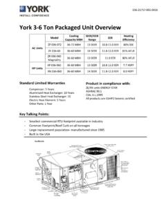
6 For combustible floors only when used with special ContactNoNoYesCabinet Size A (in) B (in) All 'B' Cabinet Furnaces 17-1/2" 16-3/8" All 'C' Cabinet Furnaces 21" 19-7/8" All 'D' Cabinet Furnaces 24-1/2" 23-3/8" QUICK REFERENCE GUIDE96% TWO STAGE PSC MULTI-POSITION RESIDENTIAL GAS FURNACES (33 TALL)Subject to change without notice. Printed in 2009 by Johnson Controls, Inc. All rights : 505310-URG-A-0409 Johnson Controls Unitary Products5005 York DriveNorman, OK 73069*505310*Furnace is multi-position and may be installed in any of the configurations that all PVC venting has at least 1/4 per foot slope towards the furnace condensate pan is self priming and contains an internal not install an external condensate trapWhen drain hose routing changes are required (shown in red)
7 , be sure to capall unused rerouting hoses - excess length should be cut off so that no sagging loops willcollect and hold condensate, which will cause the furnace to not rain gutter hoseto this LEFTMove pressure switchhose to this : May require thelonger hose that isprovided with condensate drainconnection to the 90 fitting condensate drain hose to this rain gutter hose to this positionNOTE: May require hose extension thatis provided with wider condensate drainhose to this downflow applications, the gasvalve must be rotated must be rotated 90 ineither direction for this RIGHTMove pressure switchhose to this condensate drainconnection to the 90 fitting rain gutter hoseto this condensate drainhose to this raingutter hoseto this pressure switchhose to this.
8 May require thelonger hose that is providedwith wider COMMON INSTALLATION CONFIGURATIONS (MORE OPTIONS AVAILABLEWHICH IS COVERED IN THE INSTALLATION MANUAL)WITH INDUCER ROTATION,RainGutterHosePressureSwitchHos eCondensateDrain HoseFor 100 & 120K input furnaces, the condensatedrain is factory set toward the left casing 060 & 080K input furnaces, the condensatedrain is factory set toward the right casing CONFIGURATION INFORMATION:1234125431234In upflow and downflow installation - Condensate drain hose may go out either rain gutter hoseto this position.