Transcription of Quick-Release Tail Vise - Veritas Tools
1 Tail VisePatent PendingIntroductionThe Veritas Quick-Release Tail vise is a reworked version of the well-known tail vise that is generally built into the front apron of many cabinetmaking workbenches. While workpieces can be clamped in the sliding jaw, the Quick-Release tail vise is primarily used in conjunction with bench dogs, either on top of the workbench or along the side of main problem with most sliding tail vises is that they require a signifi cant amount of work to install them. Generally, retrofi tting a tail vise onto an existing workbench requires extreme modifi cations to the workbench, and a new workbench that is to incorporate a sliding tail vise must be designed around the vise s Veritas Quick-Release Tail vise has been specifi cally designed to simplify the installation process.
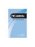
2 The vise mechanism is mounted onto the underside of a workbench top and a user-made jaw ( , a slab of material with dog holes) is attached to the vise features a Quick-Release mechanism for fast adjustment of the opening. The positive action of the mechanism means the vise can be used for spreading workpieces apart, as well as for clamping them. As delivered, the vise is confi gured for mounting on the right end of a workbench; however, it can easily be reconfi gured for mounting on the left end ofa 1: The Veritas Quick-Release Tail vise mechanism, shown upside ScrewHalf Nut CamHandleBack End PlateTeeGuide RodHandle End CapHalf NutBase CastingBushingMounting PlateO-RingQuick- release SpringQuick- release LeverQuick- release ShaftFront End Plate2 Veritas Quick-Release Tail ViseRequirementsWarning: Please read the instructions before you begin installing the Quick-Release tail vise onto your workbench.
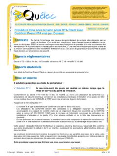
3 While the vise has been designed with ease of installation as a primary requirement, the instructions offer critical information to facilitate the Quick-Release tail vise should be mounted onto a workbench with a front apron. The mechanism requires a clear area, at least 17" 61/2", on the underside of the workbench top. The (user-made) jaw for the vise will make up part of the apron, so these two components will share jaw/apron should be at least 3" deeper than the thickness of the workbench top. It should also be thick enough to accommodate a set of dog holes. Preparing the JawFigure 2 shows a jaw designed (with 3/4" dog holes) to be mounted on the right end of a 2" thick workbench 1: To reconfi gure the vise for mounting on the left end of a workbench, remove the tee and attach it to the other end of the main shaft.
4 Use a bit of masking tape across the half nut cam and half nut to maintain their relative orientation and then swap the Quick-Release lever and the Quick-Release 2a: If you are preparing a jaw for a workbench that is not 2" thick, use the bold dimensions shown on the (left) end view of Figure 2 to vertically locate the mounting 2b: The bevelled cut on the right end of the jaw is optional and may be easier to determine after installation. The cut is confi gured so that the top edge of the jaw aligns with the top edge of the workbench (see Figure 10).Figure 2: Dimensions for a standard jaw for a 2" thick "1"5/8"2"55/8"171/2"1523/32"37/8"1"2"25/ 8"27/8" 3/4" Thru 3/4" Thru 13/32" Thru 1"Thickness of Bench(2" typ.)See Note 2b "Bottom of Bench3 Veritas Quick-Release Tail ViseTip: Leave a bit of material on the top and front of the jaw, then plane it fl ush with the apron and workbench top after fi nal assembly.
5 Attach the jaw to the mechanism using the 3/8" 13/4"long hex bolts and 3/8" the Underside of the Workbench TopTip: Flip the workbench upside down to make it easier to install the : The mounting plate location shown in Figures 4 and 5 leaves the front plate proud of the end of the bench. This location prevents the creation of a pinch point between the top of the plate and the bottom of the bench. If mounting the vise differently, be sure to consider where to leave clearance, or remove material, to avoid creating a pinch vise mounting plate must be accurately positioned onto the underside of the workbench top. Extreme care must be taken at this step, as there is very little room for error. Locate the mounting plate on the bottom of the bench, as shown in Figure 4. The large corner chamfer on the plate should be adjacent to the outer corner of the bench.
6 The front edge of the plate should be set back from the front edge of the bench by 1/4". Be sure the front edge of the plate is parallel to the front edge of the bench. Carefully transfer the six mounting screw locations. Tip: Use a transfer punch or a hinge center punch to locate and mark screw centers onto the underside of the workbench : This position for the plate will result in a 1/32" clearance gap between the jaw and the bench top to accommodate any slight misalignment, as well as any seasonal wood : For left-hand installation, fl ip the plate over so the large corner chamfer is adjacent to the outer corner of the appropriate pilot holes for the six #14 11/4"fl at-head screws (7/32" in hardwood, 3/16" in softwood). Also drill the two holes for the front lag screws (5/16" in hardwoods, 9/32" in softwoods), as shown in Figure 5.
7 Attach the mounting plate using the #14 fl at-head screws, as shown in Figure 3: Attach jaw to 5: Mounting hole 4: Aligning mounting plate and transferring screw hole locations (right-hand mounting shown)..3/8" Flat Washer3/8" 13/4" Hex BoltVise Jaw17/32"3/4"51/2"1"43/64"61/4"21/8"Fron t Lag Screw HolesMounting Screw Holes51/4"17" 61/2" Clear AreaMounting PlateBench Front EdgeLarge Corner ChamferMounting Screw Holes1/4" OffsetApron4 Veritas Quick-Release Tail ViseUse the mounting plate as a drill bushing, and drill a 5/8" diameter by approximately 1/8" deep counterbore in the bench pilot holes for the rear lag bolts, centered in the : Be careful not to damage the mounting plate as you drill the bushing counterbores; otherwise, the bushings will be diffi cult to drive into the assembled vise using the front lag screws, as shown in Figure 7.
8 The lag screws should be tightened only enough to ensure the base casting is snug to the mounting plate. Check that the bushing holes in the base casting and the mounting plate the bushings through the base casting and mounting plate. This fi t is extremely tight. If you need to use a hammer to drive the bushings into place, position a short length of wood between the bushing and the hammer to avoid damaging the rest of the mechanism. Install the rear lag screws and tighten all the lag the HandleInsert the handle into the tee, slide an O-ring onto each end of the handle, then attach the end caps with the #8 screws, as shown in Figure 9. (The O-rings will protect the end caps from banging into the tee as the handle is rotated.)Figure 6: Installing the mounting plate and drilling bushing 9: Installing the 7: Installing front lag screws.
9 Do not fully tighten the lag 8: Installing the bushings and rear lag screws. Fully tighten all the lag screws.#8 11/2" Flat-Head Wood ScrewO-RingHandle End CapHandle5/8" counterbore using mounting plate holes as drill bushing.#14 11/4" Flat-Head Wood Screw3/8" 31/2" Lag Screw3/8" Flat Washer3/8" 2"Lag Screw3/8" Flat WasherBushing5 Veritas Quick-Release Tail ViseTesting the Installation and Installing the ApronRelease the jaw and test the mechanism to ensure the vise can travel fully without excessive binding. (Note that a bit of drag between the jaw and the workbench is acceptable.) If the vise binds, you can remove the jaw and lightly plane down the surface that contacts the bench top, or install shims between the jaw and the mechanism. Alternatively, you could lightly plane the edge of the : Since the half nut is usually activated by gravity, the Quick-Release mechanism will not work while the bench is upside down.
10 To test the motion of the vise , you will have to manually pull the half nut out of the workbench back to its upright position. Back the vise off slightly (one or two turns) and install the apron so that the jaw clamps up to the apron before the vise uses its full TouchesPlane the front face of the jaw so that it is fl ush with the apron, and plane the top surface of the jaw and apron so that it is fl ush with the workbench the desired fi nish to the jaw and Quick-Release tail vise is a fairly simple device. Workpieces can be clamped between the jaw and the apron; however, it is more common to clamp workpieces between bench dogs, either on the top of the workbench or along the front of the bench, if appropriate dog holes have been drilled in the novel feature of this vise is the Quick-Release half nut.