Transcription of QUICK START GUIDE FOR YOUR DIGITAL GAUGE SYSTEM
1 MAN 650543:A QUICK START GUIDE dakota DIGITAL HDX INSTRUMENT SYSTEM This GUIDE is designed to get you up and running quickly with the minimal amount of options installed. It shows a typical and abbreviated wiring diagram as well as how to set up your speedometer, tachometer, and fuel sensor. A detailed description of all the wiring and connections can be found in the full instruction manual. Mount the display panel into your dash. (see mounting instructions or manual) Install the supplied senders. (see sensor pack manual) Mount and wire the control box. (see diagram on this sheet or see manual for more detailed descriptions) Setup the control box by selecting fuel sensor and programming speedometer.
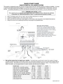
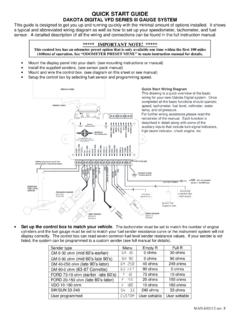
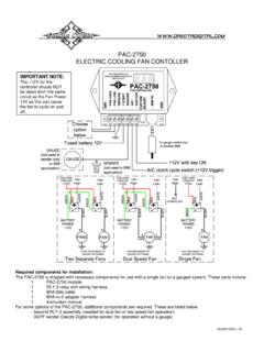
2 DISPLAY PANELEXSISTINGFUEL LEVELSENSORREDWHITEBLACKREDBLACKA dditional ground wire to fuelsensor body or mounting SENSOR SEN-03-8 0-100 PSITEMP SENSOR SEN-04-5 100-300 FPULSE GENERATORECU/ECMS peed OutputREDWHITEBLACK+12V KEY ON POWER (fused 5 - 20 AMP max)Connect to main chassis groundIgnition Coil(negative side) - +ECU/ECMor Ignition Box(tach output)SPEED SENSORSEN-01-516k PPM+12V CONSTANT POWER (fused 5 - 20 AMP max)BARECLOCKPANELRESERVED(SEE MANUAL)SIGGNDPWRSIGGNDDRNSIGGNDSIGGNDPWR SIGGNDSPD OUTTACH OUTCRUISETACHTACH WARNIGNITION PWR12 VDC CONSTANTGROUNDSTATUS WAIT GEAR 4x4 RIGHT LEFT HIGH BRAKE ENGINEDIM EXTRA EXTRA WARN READYBTSW:RIGHTSW:LEFTDISPLAYCABLEBUZZER Q uick START Wiring DiagramThis drawing is a QUICK overview of the basicwiring for your new dakota DIGITAL HDX completed all the basic functions shouldoperate; speed, tachometer, fuel level, voltmeter,water temp, and oil further wiring assistance, please read theremainder of the manual.
3 Each function isdescribed in detail along with some of theauxiliary inputs that include turn signal indicators,high beam indicator, check engine, etc. Set up the control box to match your vehicle. The tachometer must be set to match the number of engine cylinders and the fuel GAUGE must be set to match your fuel sender resistance curve or the instrument SYSTEM will not display correctly. The control box can read 10 common fuel level sender resistance values. If your sender is not listed, the SYSTEM can be programmed to a user settable sender (see full manual for details). Fuel Sender type Menu Empty R Full R GM 0-30 ohm (mid 60 s-earlier) GM 0-30 0 ohms 30 ohms GM 0-90 ohm (mid 60 s-late 90 s) GM 0-90 0 ohms 90 ohms GM 40-250 ohm (late 90 s-later) GM 40-250 40 ohms 249 ohms GM 250-40 ohm GM 250-40 249 ohms 40 ohms GM 90-0 ohm (63-67 Corvette) 63 VETTE 90 ohms 0 ohms FORD 73-10 ohm (earlier -late 80 s) FORD 73-10 73 ohms 10 ohms FORD 20-150 ohm (late 80 s-later) FORD 20-150 20 ohms 150 ohms VDO 10-180 ohm VDO 10-180 10 ohms 180 ohms SW/SUN 33-240 SW 240-33 240 ohms 33 ohms ASIA 112-4 ohm (various imports) ASIA 112-4 112 ohms 4 ohms User programmed MANUAL ADJ User settable User settable ** IMPORTANT NOTE!
4 ** This control box has an odometer preset option that is only available within the first 100 miles of driving. See ODOMETER PRESET MENU in main instruction manual for details. MAN 650543:A Setup continued 1. With the ignition key on, touch and hold both switches on the display panel. 2. The message display will show ENTER SETUP with a scrolling bar. Once SETUP RELEASE is shown, release both switches. 3. Tap the right switch until TACH is highlighted in the center. Press and hold the switch until RELEASE is shown. 4. Now you can tap either switch to scroll through the tach sub-menus, INPUT , UPDATE RATE , SHIFT LIGHT , or BACK . Tap either switch until INPUT is highlighted then hold the switch until RELEASE is shown.
5 Tap either switch until CYLINDER is highlighted and hold the switch until RELEASE is shown. The current engine cylinder setting will be displayed, 01-16 or BUS. Tap the switch until the desired setting is displayed then hold the switch until RELEASE is shown. If the engine is running the tachometer needle will update as the settings are changed. Tap the switch until BACK is highlighted then hold the switch until RELEASE is shown. Repeat selecting BACK once more to get back up to the main menu. 5. Tap the right switch until FUEL is highlighted in the center then hold the switch until RELEASE is shown. 6. Now you can tap either switch to scroll through the fuel sub-menus, INPUT , RANGE , or BACK Tap either switch until INPUT is highlighted then hold the switch until RELEASE is shown.
6 The current fuel sender selection will be shown. Tap the switch until the desired sensor is highlighted. The fuel needle will update as you change settings and the message display will indicate if the sensor input is in range for the current selection. When the desired setting is displayed, press and hold either switch until RELEASE is shown. 7. To quit and exit, turn the key off. The tach and fuel should now be set. Calibrate the speedometer. You must also calibrate the speedometer, failing to do so could cause accelerated accumulation of odometer miles. The setup procedure described below is for use with the supplied sensor, see full manual for other options. (auto-cal method listed, see full manual for more) 1.
7 START the engine. Once the engine is running, press and hold both switches on the display panel. 2. The message display will show ENTER SETUP with a scrolling bar. Once SETUP RELEASE is shown, release both switches. 3. Tap the right switch until SPEED is highlighted in the center. Press and hold the switch until RELEASE is shown. 4. Now you can tap either switch to scroll through the speed sub-menus, AUTO CAL , ADJUST , SERVICE , UNIT , INPUT , OUTPUT , or BACK . Tap either switch until AUTO CAL is displayed then hold the switch until RELEASE is shown. The message display should read AUTO CAL and DRIVE 1 MI with a 0 below it. Begin driving one measured mile. The number below DRIVE 1 MI should START incrementing as you travel, indicating the pulses received from the speed sensor or VSS.
8 Once you reach the end of the marked mile, or are passing the marker, tap either switch to finish and save the new calibration. Auto Cal is now complete and your speedometer should be reading correctly. WARNING: This product can expose you to chemicals including lead, which is known to the State of California to cause cancer and birth defects or other reproductive harm. For more information go to