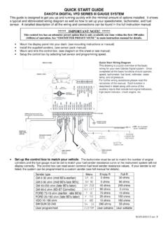
Transcription of Quick Start Guide - iOptron
1 1 iOptron Corp. | 6E Gill Street | Woburn, MA 01801 USA | (781) 935-2800 | Quick Start Guide The iEQ45 Pro GoTo German Equatorial Mount #8000E, #8000EP and #8000E-AZ PACKAGE CONTENTS1 Telescope Mount (with built-in GPS) Losmandy/Vixen dual saddle Go2 Nova 8407+ Hand Controller Two 5 kg Counterweight Controller Cable X 2 LED with cable for Polar Scope AC adapter (100V-240V) 12V DC adaptor cable with car lighter plug RS232 to RJ9 cable 2-inch Tripod (8000Z) Pier (8000E-AZ and 8000EP) AZ base (8000E-AZ) Vertical Locking Knob (8000E-AZ) ONLINE CONTENTS (click under Support menu) Manuals (you will need to refer to the full manual for details on set-up and operation). Tips for set up Hand controller and mount firmware upgrades (check online for latest version) Reviews and feedback from other customers 1.
2 Actual contents, specifications and color may vary. Please refer to iOptron website for latest information. 2 iOptron Corp. | 6E Gill Street | Woburn, MA 01801 USA | (781) 935-2800 | Quick Setup 1. Removing the Mount from the Package: The mount is shipped with axis released to avoid gear damage. Please tighten the top two Locking Screws before pull the mount out of the package. 2. A. Setting Up Tripod: Expand the tripod legs and lock the Tripod Spreader so that the tripod legs stay open (Figure 1). Adjust the tripod height by unlocking and re-locking the tripod legs to desired height. Position the tripod so that the Alignment Peg faces north. (The Alignment Peg may be moved to the opposite position if used at latitude lower than 20 to avoid counterweights hitting the tripod leg) Figure 1 1.
3 B. Setting Up Pier: Unthread the Pier Locking Screw (This screw is only used for pier storage). Separate the Pier Base with Legs from the Pier Tube. Remove the Pull Rods from inside the pier. Figure 2 Figure 3 Move the Pier Foot from the end to the side. Figure 4 Spread the Pier Leg. Put the Pier Tube onto the Pier Base, with Pier Alignment Slot aligned over the Alignment Tab on the Pier Base. Figure 5 Adjust the length of the three Pull Rods. Hook one end of a Pull Rod onto a bolt located on the Pier Leg and the other Pull Rod end onto the mounting beam inside the Pier Tube. Evenly tighten the Pull Rods. Make sure there is no gap between the Pier Base and Pier Tube. Alignment Peg Tripod Spreader Tripod Lock Pier Locking Screw Pier Base Pier Tube Pull Rods Pier Foot Pier Foot (Storage Position) Pier Leg Pier Base Align Slot Align Tab 3 iOptron Corp.
4 | 6E Gill Street | Woburn, MA 01801 USA | (781) 935-2800 | Figure 6 Position the pier with Alignment Peg face north. Figure 7 2. Attaching the Mount: Back out the Azimuth Adjustment Knobs (next to the Bubble Level Indicator) to prevent blocking the Alignment Peg (Figure 8). Put the mount onto the tripod head (or pier top) with bubble level on top of the Alignment Peg (Figure 9). Secure the mount head by tightening Azimuth Locking Screws. Level the mount by adjusting individual tripod leg (or pier foot). You may use the build-in Bubble Level Indicator or an external level to check leveling. Az. Adjust. KnobBubble Level IndicatorAz. Locking Screw Figure 8 Figure 9 3. Setting the Latitude: Unlock the four Clutch Screws and rotate the mount 180 around the axis (Figure 10) to move the dovetail face upside.
5 Tighten the Clutch Screws. Un-screw the Latitude Adjustment Lever from Latitude Adjustment Knob (Figure 11). Turn the Latitude Adjustment Knob to set your current latitude, which is displayed in Latitude Mark Window. Use the Lever for fine adjustments as needed. Always set the latitude without the load. AxisPolar Clutch Screw (4)Dovetail Saddle Figure 10 If your latitude is between 35 to 70 , set the Latitude Adjustment Knob to the upper position. The factory default position is set at 5 to 40 . A Latitude Safety Block has to be installed for low latitude setting (Figure 11) If your latitude is between 35 to 70 , take the Latitude Safety Block off. Set the Latitude Adjustment Knob to the upper position. You should change the position before attaching the mount to the tripod head.
6 Tighten evenly Adjustable Feet Alignment Peg Alignment Peg 4 iOptron Corp. | 6E Gill Street | Woburn, MA 01801 USA | (781) 935-2800 | Latitude Adjustment KnobLat. Adjust. LeverUpper PositionLower PositionLat. Mark WindowLat. Locking Screw (X4) Lat. Safety LockLocking Screw Figure 11 4. Installing the Counterweight (CW) Shaft: Unscrew the CW shaft from the top of the mount (Figure 12 top) and thread it into the opening of the DEC axis (Figure 12 bottom). Figure 12 5. Installing the Counterweight(s): iEQ45 Pro comes with two 5kg counterweights. Use one or both of them for your particular OTA (Optical Tube Assembly). Release all Clutch Screws to set the axis free before loading the CW. An optional CW shaft extension or additional CW is available for purchase at if the payload is over 10kg.
7 6. Balancing the Payload: After attaching the scope and accessories, the mount must be balanced in both and DEC axes to ensure minimum stress on the mount driving mechanism. There are four (4) Clutch Screws and one DEC Clutch Lever. Please refer to the full manual for balance procedures/tips. 7. Connecting Cables: Attach one end of an RJ-11 cable into the socket on the side of the DEC unit and the other end into the DEC socket located on RA unit. Use another RJ-11 cable to connect the hand controller to the HBX socket located on the RA unit. Plug 12V DC power supply into the POWER socket on RA unit. The red LED will be on when the power switch is turned on. 8. Setting Controller: The time and site information of the observation location needs to be entered for precise GOTO.
8 Turn the mount power on. Press the MENU button; then Settings => Set Time & Site . Figure 13 You may enter the date using arrow keys and number keys or waiting for GPS OK. Check if it is Daylight Saving Time. Enter your time zone (add or subtract 60 minutes per time zone) by entering minutes behind UT or ahead of UT, such as: Boston is 300 minutes behind UT Los Angeles is 480 minutes behind UT Rome is 60 minutes ahead of UT Sydney is 600 minutes ahead of UT All the time zones in North America are behind UT. GPS will update your observation longitude and latitude coordinate. Or you may find them from your GPS navigator, a GPS capable cell phone or from internet. W/E means western/eastern hemisphere; N/S means northern/southern hemisphere; d means degree; m means minute; and s means second.
9 Use number keys and arrow keys to enter your location information. Move the cursor to the end of the screen to select Northern or Southern Hemisphere. 9. Polar Alignment: Remove both Polar Scope and polar axis covers. Look through the polar scope to locate Polaris (or Sigma Octantis at southern hemisphere). Slightly loosen the Azimuth Locking Screws and Latitude Locking Screws. Use the two Azimuth Adjustment Knobs to center the pole star in the azimuth direction. Use the Latitude Adjustment Knob for the latitude adjustment. Tighten the screws after adjusting. Quick Polar Alignment: Fast and accurate polar alignment can be performed with iOptron s AccuAlign Polar Scope. 5 iOptron Corp. | 6E Gill Street | Woburn, MA 01801 USA | (781) 935-2800 | (1) Thread the dark field illuminating LED into the thread-in hole on a polar scope.
10 Plug the LED cable into the Reticle socket located on the RA unit. Turn the mount power on. Use Hand Controller ( Settings => Set Eyepiece Light ) to set the illumination intensity. (2) Use the or button to turn the DEC axis to unblock the Polar Scope view (there is a hole on the DEC axis). You may loosen the DEC clutch to turn the DEC axis without rotating the telescope; (3) Use the or button to turn the RA axis to rotate the Polar Scope dial to a clock position where 12 is at the top, as shown in Figure 14. You may release the Locking Screws and hold the OTA while turning the axis; Figure 14 (4) Use Hand Controller (MENU => Align => Pole Star Position ) to display the Polaris Position on the LCD screen, as indicated in Figure 15 (a).