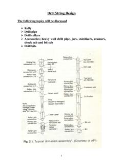
Transcription of QUIKA FLOOR Construction Guide - CAD TECH
1 Rainwater SolutionsRainwater SolutionsFencing SolutionsFencing SolutionsRoofing & Walling SolutionsRoofing & Walling SolutionsCustomer SupportCustomer SupportStructural SolutionsStructural SolutionsHome ImprovementsHome ImprovementsHouse Framing SolutionsHouse Framing SolutionsConstruction of a LYSAGHTQUIKA- FLOOR flooring is a LYSAGHT QUIKA - FLOOR ?LYSAGHT QUIKA -FLOORis a fully engineeredand certified steel sub- FLOOR the steel alternative toconventional timber bearers and joistsand is suitable for both brick veneer andfreestanding houses with a maximum fallof land of m. Bearers and joists havea large spanning capacity, typically up to2700 is comprised ofthe following components: Hot dipped galvanised UNI-PIERS ,each adjustable up to 200 mm Galvanised steel bearers, generally150 mm deep ZINCALUME steel joists, 120 mm deep Galvanised load bearing QUIKA Joists,120 mm deep Accessories such as load bearingangles, angle bracing, bracketry, and Guide2 EachQUIKA- FLOOR system is suppliedwith a bill of materials which lists theitems that are delivered with the the items delivered againstthe bill of materials.
2 If any items aremissing, contact your BLUESCOPELYSAGHT supply centre. UNI-PIER connections specificationappropriate to the wind rating(useUNI-PIER specification tables)of the building UNI-PIER load capacityspecification (appropriate to thewind rating of the building) UNI-PIER bracing specification Design data for a LYSAGHT QUIKA - FLOOR flooring system Tek Screw gun with hexagonsocket to suit 14 gauge 150 mm extension bit isuseful. Nail gun to suit Duo Fast ,Senco orMax hardenedtwist nails 230 mm angle grinder and metalcutting disc Cartridge glue gun Impact drill and 12 mm masonrydrill bit Adjustable spanner String line Tape measure A level (water level, dumpy levelor laser level)Tools for the jobUNI-PIERSare supplied in lengthincrements of 200 mm.
3 The lengthranges are: for 65 x 65 x 2 mm UNI-PIERS:from 200 to 2800 mm; for 75 x 75 x mm UNI-PIERS:from 400 to 4000 of materials 17722 16 June 2002 Company: ########################### ####LocationProductQty#### ########## ########## ######## ########## ######## ########## ######### ########## ######## ########AQUIKA- FLOOR system will typicallyconsist of most or all of thefollowing items:PiersUNI-PIERSB earers150 mm QUIKA -BEARERJ oists120 mm QUIKA -JOISTLoad-bearingLL12025joistsCorn er To brace externalBracketscorners against rackingQuika-BearerUsed to preventBracketspoint load crushing at the end of bearersLoad-bearingSupplied in mangleslengthsBracingStrap or angle bracing Vice grips or G-clamps Safety goggles Earmuffs Gloves suitable to handle steel Earth leakage circuit breaker Work boots Felt-tip marking penChoosing the correct UNI-PIERThe maximum allowable adjustmenton each pier is 200 mm.
4 Beforeordering, establish the distancefrom the top of each footing to theunderside of each bearer, and orderyour piers to fit within the various200 mm ranges. For example, if theactual height is 675 mm: use a600 mm the itemsRelated documents3 Preliminary check Establish the height to be used forthe bottom of the bearers(commonly it will be 270 mm belowthe underside of the finished FLOOR ). For brick veneer Construction ,check overall dimensions and levelsof brickwork. Using the Pier and Bearer Layout(supplied by BLUESCOPE LYSAGHT),position the bearers on the for brickveneer and brick skirting wallconstructionsScrew a QUIKA -BEARER bracket at theend of each bearer with at least fourscrews (Fig 1).
5 It may be necessaryto install additional QUIKA -BEARER brackets if a point load is locatedalong a bearer. If the point load issubstantial, an additional pier maybe needed. Ensure a damp course is fitted according to the appropriate positions of piersUsing the Pier and Bearer Layout,mark the location of the UNI-PIERson the footings. Each alternate UNI-PIER base-plate should be set atright angles to the previous one toassist piers to footings FixUNI-PIER base plates to concrete footings with twogalvanised Dynabolts 125 x 12 mm(don t tighten them yet). Refer to the UNI-PIER connection specification, or Cast the UNI-PIER into the footing;ensuring the concrete is aboveground level and slopes away fromthe on the bearers External bearers have the web tothe outside (Fig 1).
6 For brick veneer Construction : thefirst bearer is set with the web150 mm in from the outside face ofbrickwork. The ends of remaininginternal bearers are 150 mm in fromthe outside of the brickwork. For clad Construction with a brickskirting wall: bearers are set flushwith the outside of brickwork. For freestanding Construction :bearers are set flush with theexternal face of the DynaboltsTighten the Dynabolts in the UNI-PIER footings. Grout under any bearers and fix-off headsRaise the bearer to its final correctheight and check it is each UNI-PIER head to its post asdescribed in the appropriate UNI-PIERC onnection Specification. Typicallyfour screws are required for nonload-bearing piers, and eight screwsfor load-bearing the brickwork is not level, bearersmay have to be packed-up overengaged joistsLoad-bearing joists are used tosupport load-bearing walls along theperimeter of a house.
7 They aresupplied in stock lengths and mayneed cutting to length on site. Thelocations of load-bearing joists areshown on the Joist Layout (suppliedbyBLUESCOPE LYSAGHT).Lay a load-bearing joist on its weband pre-drill the flange where itintersects a load-bearing joist with theweb to the outside (Fig 3). With theend of the joist flush with theoutside bearer, screw the joist inplace with two screws through thepre-drilled holes (Fig 3). QUIKA JoistsSet-out and mark the positions onthe bearers for joists at 450 mmcentres, measuring from the outsideof the load-bearing that joists don t protrudepast the edge of the bearersotherwise they will interfere withload-bearing the joists on the bearers, overthe set-out marks.
8 Place one screwin one end of a joist, check theposition of the other end, and placetwo screws. Place the second screwat the first end (Fig 4).Check that the joists are straightbefore fixing at each bearer with two screws. Tie Down ProcedureBearer to brickwork tie down shallbe in accordance with local 2 Figure 4 QUIKA -JOISTQUIKA-BEARERSet-outmarkQUIKA- BEARERQUIKA-BEARER bracketLoad-bearingjoistFigure 3We bFlangeConstruction proceduresQUIKA-BEARER bracketQUIKA-BEARERWe bFigure 1 FlangeCutting and clean-up of materialsCut materials over the ground and not over othermaterials. Sweep all metallic swarf and otherdebris at the end of each day and at thecompletion of the a bearer on theUNI-PIER heads,aligning the ends as mentionedpreviously.
9 Level the at a time, raise a UNI-PIER headto the bearer. With the UNI-PIER headhard up under the bearer, and thepost vertical, fix the UNI-PIER head tothe bearer as described in therelevantUNI-PIER connectionspecification typically 2 screws for non-load bearing and 4 screwsfor load bearing (Fig. 2) Refer to theUNI-PIER connection specificationfor 6 Fix bracing20 mm downfrom ant capand20 mm upfrom baseAnglebracingBearer braceMain bearerGeneralpurposebracketUse 14 x 20 x 22 mmscrewsLoad-bearing anglesFit load-bearing angles to the endsof joists as shown on the JoistLayout. These angles are suppliedin m lengths so you may haveto cut the last at the place where youstarted the set-out for the joists.
10 (As a check on your joist layout,the end of a full-length angleshould align with the centre of ajoist (Fig 5).Push the angle down firmly on top of the joists, and fix intothe web of the bearer with one14 20 x 22 mm screw on the mid-span of every joist (Fig 5). Do not fix at the external cornersbecause the screws will foul thecorner internal corners, it may benecessary to install an offcut ofload-bearing joist to support theend of the load-bearing angle. Fixoffcuts with two 14 20 x 22 mmscrews (Fig 6). Copyright BlueScope Steel Limited 22 September 2003 LYSAGHT andZINCALUME are trademarks of BlueScope Steel Limited 16 000 011 058 TheLYSAGHT range of products is exclusively made byBlueScope Steel Limited trading as BlueScope , brochures andyour local distributor1800 641 417 Please check the latest informationwhich is always available , Uni-Pier and the Uni-Pier logo are owned by QUIKA - FLOOR Pty Ltd and are used under licence byBLUESCOPE LYSAGHT.)