Transcription of R 2ND GENERATION ELECTRIC ACTUATOR …
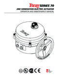
1 TheHighPerformanceCompanyRSERIES 702ND GENERATION ELECTRIC ACTUATOROPERATION AND maintenance MANUALBRAY Series 70 ELECTRIC ActuatorOperation and maintenance ManualTABLE OF CONTENTS:PAGEINTRODUCTION2 PRINCIPLE OF OVERRIDE TO A ACTUATOR LIMIT SWITCH AND MECHANICAL TRAVEL STOP DISASSEMBLY AND ASSEMBLY INSTRUCTIONS4 FIELD OR FACTORY INSTALLABLE OPTIONSTORQUE SWITCHES PLUS II FEEDBACK (TYPICAL WIRING DIAGRAMS) FORM C (SPDT) SWITCHES .. 10 QUICK CONNECT CONTROL ABASIC BACTUATOR TROUBLESHOOTING TROUBLESHOOTING CEXPLODED VIEW AND PARTS LIST OF SIZE 003 AND VIEW AND PARTS LIST OF SIZE 008, 012 AND VIEW AND PARTS LIST OF SIZE 030, 050 AND INFORMATION ON THIS PRODUCT AND OTHER BRAY PRODUCTSPLEASE VISIT US AT OUR WEBPAGE - Series 70 ELECTRIC ActuatorOperation and maintenance Manual2 INTRODUCTIONThe Bray Series 70 is a quarter turn ELECTRIC ACTUATOR withmanual override for use on any quarter turn valve requiringup to 6500 in lb of torque.
2 Operating speeds vary between6 to 60 OF OPERATIONThe Series 70 ACTUATOR is basically divided into two internalsections; the power center below the switchplate, and thecontrol center above the switchplate. Below the switchplatethe capacitor and gearmotor with its spur geartrain drive a finalnon-backdriveable worm gear output. The override mecha-nism for manual operation is also housed here. Above theswitchplate is where user required, readily accessible compo-nents are placed. The camshaft assembly, limit switches,terminal strips, torque switches, heater, and servo are allplaced here for easy access. External to the unit are foundadjustable mechanical travel stops, a large easy to readindicator, the unique manual override handwheel and dualconduit entry ports.
3 The external coating is a high qualitypolyester powder coat which has exceptional UV as well aschemical OPERATIONThe motors used in the Bray Series 70 are either permanentinduction split capacitor design (single phase AC power), SCI(Three Phase AC Power) or PM (DC Power). Travel limitswitches are mechanical form (SPDT) with contacts rated at10 amp ( PF), 1/2 HP 125/250 VAC. In cases where thetorque capacity of the unit is exceeded to the point where themotor stalls and overheats, a thermal protector switch builtinto the motor windings will automatically disconnect themotor power. Once the motor cools sufficiently the thermalprotector switch will reset. Optional torque switches are avail-Use this chart as a guide to interpret the S70 ELECTRIC ACTUATOR part NUMBERING SYSTEM REFERENCE CHARTPART NUMBERTORQUESPEED, 1/4 TURNSUPPLY( )(Seconds)(Z Voltage)
4 70-003X-113yz-53630060/30/150/1/2/3/470- 005X-113yz-53650060/30/150/1/2/3/470-008 X-113yz-53680030/15/10/60/1/2/3/4/5/6/7/ 870-012X-113yz-536120030/15/10/60/1/2/3/ 4/5/6/7/870-020X-113yz-536200030/150/1/2 /3/4/5/6/7/870-030X-113yz-536300030/180/ 2/3/4/5/6/7/870-050X-113yz-536500030/180 /2/3/4/5/6/7/870-065X-113yz-5366500300/2 /3/4/5/6/7/8Y - DESIGNATES STYLEA= DECLUTCHABLEB = NON DECLUTCHABLE01234120 VAC 12 VDC24 VDC 24 VAC 220 VACX - DESIGNATES THE SPEEDX= 0 1 2 2 3 4 SEC = 60 30 18 15 10 6Z - DESIGNATES THE VOLTAGEZ=VOLTAGE=5678380V400V440V480V3-P H3-PH3-PH3-PHable in all units to prevent the possibility of stalling the motor,thus reducing the necessity for an inoperable thermal cooldownperiod. Torque switches installed by Bray are factory adjustedto the output torque rating of the unit using electronic torquetesting equipment.
5 Field adjustment of the torque switches isnot Electrical Schematic(Note: this is only a reference. For the actual wiring diagram refer tothe diagram placed inside the ACTUATOR cover.)MECHANICAL OPERATIONM echanically, the ratio of the gearmotor determines the speedof the unit. The gearmotor utilizes high efficiency spur gearswith various ratios for the different speeds. Initial gearreduction through the spur gears is then transferred to theworm shaft. The final gear reduction and output is through anon-backdriveable worm gear set. Positioning is determinedby an indicator-cam shaft linked to the output shaft. In thedeclutchable style the manual override drives the worm shaftwhen OVERRIDE OPERATION (DECLUTCHABLE STYLE)The manual override operates similar to a watch adjustingknob.
6 To engage the manual override simply pull the handwheelto its outermost position. A yellow stripe is revealed for visualindication that the unit cannot run electrically. The twoCAMSNEUTRALOPENCLOSELIVEOPENCLOSEMANU AL OVERRIDE SWITCHTRAVEL LIMIT SWITCHESCAPACITORMOTORTHERMAL PROTECTORTORQUE SWITCHESFIELDWIRING(OPTIONAL)Single phase power Series 70 ELECTRIC ActuatorOperation and maintenance Manual3handwheel positions, engaged and disengaged, are held inplace with the use of spring plungers. The handwheelremains in position until physically moved. Rotating thehandwheel in the clockwise direction will rotate the outputshaft in the same clockwise (closed) direction and label on the handwheel hub warns users not to exceed aspecific rim pull force, for each size of ACTUATOR .
7 If the rim pullforce is exceeded, the roll pin securing the handwheel ontothe manual override shaft will shear, thus preventing moreserious internal gearing OVERRIDE OPERATION (NON DECLUTCHABLE STYLE)Removal of black plastic cap will reveal shaft stub withmachined flats on it to allow a wrench to grip and rotate : This shaft is directly connected to worm drive gearand electrical power must be isolated from unit prior tomanually turning STORAGEU nits are shipped with two metal screw-in plugs in order toprevent foreign matter from entering the unit. To preventcondensation from forming inside these units, maintain anear constant external temperature and supply power to theoptional heater internal to the TO A VALVEAll Bray Series 70 ELECTRIC actuators are suitable for directmounting on Bray butterfly valves.
8 With proper mountinghardware, the S70 ACTUATOR can be installed onto otherquarter-turn valves or devices. The standard mountingposition for the ACTUATOR is to orient the unit with its handwheelin a vertical plane and parallel to the pipeline. If the actuatoris to be mounted on a vertical pipe, it is recommended thatthe unit be positioned with the conduit entries on the bottomto prevent condensation from entering the ACTUATOR by wayof the conduit. In all cases, the conduit should be positionedto prevent drainage into the ACTUATOR should be mounted to the valve as follows:1. Manually operate the ACTUATOR until the output shaft ofthe ACTUATOR is in line with the valve stem. If possible,use an intermediate position ( valve disc/stem andactuator half open).2. Place the proper adapter, if required, onto the valvestem.
9 It is recommended that a small amount of greasebe applied to the adapter to ease Mount the ACTUATOR onto the valve stem. It may benecessary to swing or manually override the ACTUATOR toalign the bolt Install the furnished mounting studs by threading themall the way into the ACTUATOR Fasten in place with the furnished hex nuts and WIRINGEach ACTUATOR is provided with two (2) conduit entries (onefor power and one for control).1. The motor full load current is noted on the nameplate ofthe ACTUATOR . The terminal strip will accept wire sizesranging from 14 to 22 AWG (14 to 24 AWG for theservo). 18 AWG minimum is recommended. Note thatthe optional heaters use approximately amps at110 All actuators have their applicable wiring diagramattached to the inside of the cover.
10 Field wiringshould be terminated at the ACTUATOR terminal strip inaccordance with this wiring The conduit connections must be properly sealed tomaintain the weatherproof integrity of the ACTUATOR (PARALLEL) WIRINGDo not connect more than one S70 ACTUATOR to a SPDT switch. Avoltage is present on the opposite winding to the powered one. Ifthis winding is connected to another as shown in the INCORRECT diagram it will interfere with the motor performance. Use a multiplepole switch as shown in the CORRECT diagram.*TPTPTPTPOPENMOTORCLOSECAPACITOR CAPACITORCLOSEMOTOROPENSPDT CONTACTINCORRECTTWO SPDT CONTACTSCAPACITORCLOSEMOTOROPENCAPACITOR MOTOROPENCLOSECORRECTNo. 1No. 2No. 2No. 1122223333111 WARNING:Do not reverse motor instantaneously when it is still running-Reversing direction to ACTUATOR motor when it is running can causedamage to motor, switches and gearing.