Transcription of Radartutorial
1 Radartutorial ( ). Radartutorial Book 1 radar Basics . (Revision from ). This educational endowment is a printable summary of the first chapter of the internet representation radar Basics , containing a lecture on the principles of radar technology. Table of Contents: BOOK 1 radar BASICS .. 1. Learning Objectives .. 2. Preamble .. 2. Basic Principle of Operation .. 2. HISTORICAL OVERVIEW .. 3. radar BASIC PRINCIPLES .. 4. Signal Routing .. 5. Signal Timing .. 5. Ranging .. 6. Maximum Unambiguous Range .. 6. radar Waveforms Minimum Range .. 7. Slant 7. Direction determination .. 7. Bearing .. 7. Elevation Angle .. 8. Height .. 8. Accuracy .. 9. radar Resolution .. 9. Angular 9. Range Resolution .. 10. Resolution Cell .. 10. Theoretical Maximum Range Equation .. 11. Antenna 11. Antenna Aperture .. 12. radar Cross Section .. 12. Free-space Path Loss .. 13. External and Internal Losses .. 13. Converting the Equation .. 14. Transmitters 14.
2 MDS- Echo .. 15. 15. radar Range Equation (Example given) .. 16. False Alarm Rate .. 16. Probability of Detection .. 16. Frequency-diversity radar .. 17. 1. Radartutorial ( ). Learning Objectives The learning objectives are a preview of the information you are expected to learn in this chapter. This first chapter of the Radartutorial deals with mathematically basics of radar Technology. This chapter provides the basis for understanding the subsequent chapter on the specific sub system modules. It is intended to give a background in radar theory, including radar principles, propagation, radar signals, resolution and the radar equation. At the end of this chapter, students should understand the fundamentals of radar and recognize the key performance parameters associated with primary radar specifications. The student should be able to: explain the basic operation of a pulse radar system;. define range, bearing, and altitude as they relate to a radar system.
3 Discuss how pulse width, peak power, and beam width affect radar performance;. describe the factors that contribute to or deteriorate from radar resolution;. know the advantages of a frequency diversity radar ;. using a block diagram, describe the basic function, principles of operation, and interrelationships of the basic units of a radar system. Preamble The basic principle of operation of primary radar is simple to understand. However, the theory can be quite complex. An understanding of the theory is essential in order to be able to specify and operate primary radar systems correctly. The implementation and operation of primary radars systems involve a wide range of disciplines such as building works, heavy mechanical and electrical engineering, high power microwave engineering, and advanced high speed signal and data processing techniques. Some laws of nature have a greater importance here. Basic Principle of Operation radar measurement of range, or distance, is made possible because of the properties of radiated electromagnetic energy: This energy normally travels through space in a straight line, at a constant speed, and will vary only slightly because of atmospheric and weather conditions.
4 (The effects atmosphere and weather have on this energy will be discussed later; however, for this discussion on determining range, these effects will be temporarily ignored.). Electromagnetic energy travels through air at approximately the speed of light, 300,000 kilometers per second or 186,000 statute miles per second or 162,000 nautical miles per second. Reflection of electromagnetic waves The electromagnetic waves are reflected if they meet an electrically leading surface. If these reflected waves are received again at the place of their origin, then that means an obstacle is in the propagation direction. These principles can basically be implemented in a radar system, and allow the determination of the distance, the direction and the height of the reflecting object. 2. Radartutorial ( ). Historical Overview Neither a single nation nor a single person is able to say, that he (or it) is the inventor of the radar method. One must look at the radar than an accumulation of many developments and improvements earlier, which scientists of several nations parallel made share.
5 There are nevertheless some milestones with the discovery of important basic knowledge and important inventions: Figure 1: W rzburg Riese , World War II radar produced in 1940 by Telefunken (Germany). 1865 The Scottish physicist James Clerk Maxwell developed his electro-magnetic light theory (Description of the electro-magnetic waves and her propagation). 1886 The German physicist Heinrich Rudolf Hertz discovers the electro-magnetic waves and proves the theory of Maxwell with that. 1904 The German high frequency engineer Christian H lsmeyer invents the Telemobiloskop to the traffic supervision on the water. He measures the running time of electro-magnetic waves to a metal object (ship) and back. A calculation of the distance is thus possible. This is the first practical radar test. H lsmeyer registers his invention to the patent in Germany and in the United Kingdom. 1917 The French engineer Lucien L vy invents the super-heterodyne receiver.
6 He uses as first the denomination Intermediate Frequency , and alludes the possibility of double heterodyning. 1921 The invention of the Magnetron as an efficient transmitting tube by the US- American physicist Albert Wallace Hull 1922 The American electrical engineers Albert H. Taylor and Leo C. Young of the Naval Research Laboratory (USA) locate a wooden ship for the first time. 1930 Lawrence A. Hyland (also of the Naval Research Laboratory), locates an aircraft for the first time. 1931 A ship is equipped with radar . As antennae are used parabolic dishes with horn radiators. 1936 The development of the Klystron by the technicians George F. Metcalf and William C. Hahn, both from General Electric. This will be an important component in radar units as an amplifier or an oscillator tube. 1940 Different radar equipments are developed in the USA, Russia, Germany, France and Japan. The reasoning to use of electric magnetic waves to the locating of ships has been registered of the engineer of D sseldorf, Christian H lsmeyer, already 1904 in Germany and England as a patent.
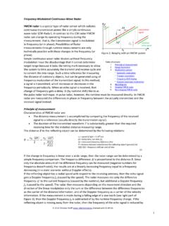
7 One finds the illustration in the patent specification of a steamer which detects an approaching ship with help of the backscattering. Tests carried out on the Rhine River had in principle yielded the usefulness of this method. Figure 2: Cover of the patent script 3. Radartutorial ( ). radar Basic Principles The electronic principle on which radar operates is very similar to the principle of sound-wave reflection. If you shout in the direction of a sound-reflecting object (like a rocky canyon or cave), you will hear an echo. If you know the speed of sound in air, you can then estimate the distance and general direction of the object. The time required for an echo to return can be roughly converted to Figure 3: radar principle distance if the speed of sound is known. radar uses electromagnetic energy pulses in much the same way, as shown in Figure 3. The radio-frequency (RF) energy is transmitted to and reflected from the reflecting object.
8 A small portion of the reflected energy returns to the radar set. This returned energy is called an ECHO, just as it is in sound terminology. radar sets use the echo to determine the direction and distance of the reflecting object. The word radar is a contraction of RAdio Detecting And Ranging As implied by this contraction, radars are used to detect the presence of an aim (as object of detection) and to determine its location. The contraction implies that the quantity measured is range. While this is correct, modern radars are also used to measure range and angle. The following figure shows the operating principle of primary radar . The radar antenna illuminates the target with a microwave signal, which is then reflected and picked up by a receiving device. The electrical signal picked up by the receiving antenna is called echo or return. The radar signal is generated by a powerful transmitter and received by a highly sensitive receiver.
9 Figure 4: Block diagram of a primary radar with the signal flow 4. Radartutorial ( ). Signal Routing The radar transmitter produces short duration high-power RF- pulses of energy. The duplexer alternately switches the antenna between the transmitter and receiver so that only one antenna need be used. This switching is necessary because the high-power pulses of the transmitter would destroy the receiver if energy were allowed to enter the receiver. The antenna transfers the transmitter energy to signals in space with the required distribution and efficiency. This process is applied in an identical way on reception. The transmitted pulses are radiated into space by the antenna as an electromagnetic wave. This wave travels in a straight line with a constant velocity and will be reflected by an aim. The antenna receives the back scattered echo signals. During reception the duplexer lead the weakly echo signals to the receiver. The hypersensitive receiver amplifies and demodulates the received RF-signals.
10 The receiver provides video signals on the output. The indicator should present to the observer a continuous, easily understandable, graphic picture of the relative position of radar targets. All targets produce a diffuse reflection it is reflected in a wide number of directions. The reflected signal is also called scattering. Backscatter is the term given to reflections in the opposite direction to the incident rays. radar signals can be displayed on the traditional plan position indicator (PPI) or other more advanced radar display systems. A PPI has a rotating vector with the radar at the origin, which indicates the pointing direction of the antenna and hence the bearing of targets. It shows a map-like picture of the area covered by the radar beam. Signal Timing Most functions of a radar set are time-dependent. Time synchronization between the transmitter and receiver of a radar set is required for range measurement. radar systems radiate each pulse during transmit time (or Pulse Width ), wait for returning echoes during listening or rest time, and then radiate the next pulse, as shown in Figure 5.