Transcription of Railway Technical Website
1 Railway Technical Website Infopaper No. 6 Basic Railway Signalling by Piers Connor1 Introduction As any train driver will attest, driving a train is easy. The difficult bit is stopping it. It s easy to get the train going but much more difficult to stop in the right place and, to do this consistently and keep time, requires skill and concentration. The reason for this is simple the adhesion available for a train with a steel wheel on a steel rail is such that the braking distance is considerably more than that obtained in a car with rubber tyres on the average road. The adhesion between a tyre and the road surface can be measured at over 85%. The UK main line railways calculate their braking distances on the basis of 8% adhesion, an order of magnitude less.
2 This sort of calculation is standard across the world. To use a comparison between road and rail braking, we can look at someone who wants to stop a car from 70mph. The driver thinks about it (20m) and then brakes (80m), requiring a total of 100m stopping distance. Now transfer this process to the cab of a train running at 70 mph. The driver reaction distance is still 20m but you have to add tome for applying the brake and allowing for it to feed up to the required pressure on the whole train, which needs another 60m. Then the actual distance for the train to stop will be another 950m approx., giving a total of 1030m, or more than a kilometre. This would represent a full service brake application with no allowances for error or a safety margin.
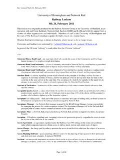
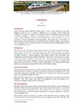
3 An emergency brake application at this speed might get the train to a stand in 700m if it s not raining. This means that a train s braking distance is likely to be an order of magnitude greater than that of a road vehicle and, for a driver in an emergency situation, it seems like a million times greater when you are at the front of a train with the emergency brake fully applied and you know there is nothing you can do to avoid hitting something in front of you. 1 PRC Rail Consulting Ltd. One of a series of papers on Technical issues published by the RTW from time to time. Figure 1: Train of Chiltern railways approaching Princes Risborough station, showing various signals providing route control indications.
4 Note also the fixed speed limit sign for movements over the crossover. Photo by Roger Marks. Infopaper No. 6 Basic Railway Signalling Railway Technical Website Page 2 Updated 7th May 2017 It is a sad fact of life that very few members of the general public understand that there is any difference between train braking and car braking, which is why a distraught mother once called a train driver in the UK a murderer when his train killed her 16-year old son who was trespassing on the Railway with his friends. She thought he had not bothered to try and stop. Of course, this wasn t the case but the local press made a big issue of it. In another instance, there were calls by some individuals for the railways to be closed down altogether after the Ufton Nervet level crossing accident on 6 November 2004, because trains aren t safe if they can t stop for a car at a level crossing.
5 Such uninformed nonsense is widespread in the public mind and the media love it. Railway companies ignore it at their peril. Urban Railway administrations in particular, must understand that a strong and carefully targeted public awareness campaign is essential for new railways and tramways if a low accident rate is to be achieved. Signals The long braking distances required by trains present a problem for the driver of a manually controlled train. He is unlikely to be able to see an obstruction or diversion requiring him to reduce the train speed or to stop. In effect, he is effectively driving blind . To overcome this, he (or she) requires advice in advance of the point where it is necessary to apply the brake.
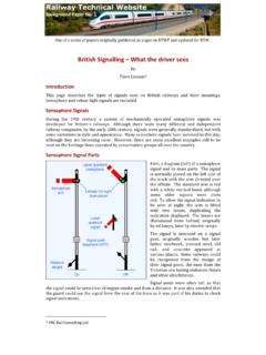
6 railways have developed such a system, which we call signalling. Traditionally, signals are provided at fixed lineside locations to indicate to the driver of an approaching train how he should proceed or, possibly, the limit of his movement authority (LMA). To achieve this, the line is divided into sections, often called blocks, and a signal is placed at the entrance to each block to act as a sort of gate keeper . The rule is that (normally) only one train is allowed into a block at any one time. Figure 2 above shows the general arrangement for a signal on a manually operated Railway . It is the practice on many railways to provide overrun space beyond the signal in the form of a margin, often referred to as an overlap.
7 This overlap can be a set distance (183m on UK main line railways ), calculated on a site-by-site basis, (London Underground) or by separating trains by a whole block length. The choice depends on the administration, traffic requirements and the type of signalling installed. Metro systems normally require signalling to include calculated overlaps or fixed block safety margins. Similar principles are being applied to main line railways as they are modernised. Figure 2: Schematic of train and signal on a manually operated Railway . Note that it is necessary to allow a reaction time between the point where the driver sees the signal and his selection of a brake application.
8 Diagram: Author Infopaper No. 6 Basic Railway Signalling Railway Technical Website Page 3 Updated 7th May 2017 There is a wide variety of fixed signals used by railways around the world. They may be categorised into two broad groups, speed signalling or route signalling . Speed signalling is the most common, where the indications for the driver represent an instruction to proceed at a speed depending on the type of train in his charge. Most administrations in continental Europe and North America have adopted this system. A driver is shown one or more lights in a specified pattern, which gives him the authority to proceed (or not) at the speed designated to his train.
9 Thus it is common for the same indication to allow a passenger train to proceed at, say, 160km/h, while a freight train is restricted to 60km/h on the same route. Some systems use variable number displays to indicate maximum speed. The route signalling system differs in that the speed limits are separate from the signalling. They are usually indicated by discrete and fixed lineside signs. Variations for different types of trains are assumed to be part of the driver s knowledge. Drivers are shown proceed indications for a block or a number of blocks ahead. If a diverging route is set, additional indications are provided and the driver is expected to adjust the train speed to comply with the separate lineside signs.
10 This system is normal UK practice and has been adopted in many overseas countries where UK Railway systems have been installed. Some administrations use a combination of the two systems, the French Railway SNCF, for example. Regardless of the system adopted, with manual driving, signal sighting will dictate the braking distances and therefore the block lengths. As train speeds increase, they require longer braking distances and therefore longer sighting distances or earlier warnings of conditions ahead. Very early on in the development of railways , routes were equipped with intermediate updates of signal information. Signalling Developments The first development was to provide advance warning of a signal s position or aspect2 by the use of a distant signal.