Transcription of Railway Technology Today 3 (Edited by Kanji Wako) Railway ...
1 Technology Technology Railway Technology Today 3 ( edited by Kanji Wako). Railway Electric Power Feeding Systems Yasu Oura, Yoshifumi Mochinaga, and Hiroki Nagasawa railways with many long tunnels or on and other countries to minimize rectifi- Introduction underground railways because the energy cation failures. Later advances in silicon efficiency is higher than steam or diesel commutator Technology paved the way for Electric power Technology in the Railway locomotives and does not involve on- AC feeding systems using commercial fre- industry refers to the means of supplying board combustion. The high tractive force quencies in France and elsewhere. The good-quality electric power to the elec- also makes electric operation suitable for 25-kV system is used widely around the tric motors.
2 It primarily consists of power lines running through hilly regions. As a world while Japan relies on a 25 kV sys- conversion Technology at sub-stations, consequence, electric train operation tem for shinkansen and a 20-kV ac feed- feeding circuits for DC and AC feeding made remarkable progress. It started first ing system for conventional' railways . (In systems, and the structure, materials, mea- with direct-current feeding systems ca- this article, conventional' means all JNR/. surement, and maintenance of the elec- pable of driving a DC motor directly and JR narrow-gauge lines, all non-JR railways , tric overhead lines. offering high tractive force and easy speed and the Akita and Yamagata shinkansen, Power collection via the overhead line control. which were converted to standard gauge and pantograph, introduced nearly 100 Although a 3000-V dc feeding system is from narrow gauge.)
3 Years ago early in the history of electric widely used in many other countries, The three-phase, alternating-current feed- railways , remains basically unchanged in some Japanese railways using DC rely on ing system is used with induction motors physical appearance. However, techno- a 1500-V dc system. in Europe for railways with steep moun- logical developments during the past cen- The other alternating-current feeding sys- tain grades, while a 600-V system, featur- tury have done much to greatly increase tem originated in Europe using a single- ing speed control by a power converter, the current capacity, speed, and safety. phase, commutator-type motor. Special is used in Japan for new urban transit sys- Today , the capacity is more than sufficient low frequencies such as 25 Hz and tems.
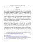
4 To drive modern super high-speed trains. Hz were introduced in Austria, Germany, This article discusses all aspects of elec- tric power supply systems for railways , ranging from the history of electrification Table 1 World Electric Railway Feeding Systems and Electrified Distances of Japanese railways to Today 's sophisti- (1996). cated power supply facilities. It also com- Japan1 World (including Japan). pares them with their counterparts in other System Type km % km % Main Countries countries. DC Less than 1,500 V 915 5 5,106 2 Germany, UK, Switzerland, USA. 1,500 V to 3,000 V 10,484 61 22,138 9 France, Spain, Netherlands, Australia World Railway (Mostly 1,500 V). Electrification Systems 3,000 V or more 78,276 33 Russia, Poland, Italy, Spain, South Africa (Mostly 3,000 V). Table 1 shows various feeding systems Single- 50 Hz Less than 20 kV 245 0 France, USA.
5 Around the world and the electrification phase . AC 60 Hz 20 kV 3,741 22 3,741 2. distances. The history of electric railways dates back 25 kV 2,037 12 84,376 36 Russia, France, Romania, India, China to 1835 when T. Davenport fabricated a 50 kV 1,173 0 USA, Canada, South Africa model electric car powered by voltaic 25 Hz 11 kV to 13 kV 1,469 1 USA, Austria, Norway cells and put it on public exhibition. The Hz 11 kV 120 0 Switzerland first practical electric cars debuted in 1879 15 kV 35,461 15 Germany, Sweden, Switzerland when a 150-V dc, , bipolar motor Three-phase AC 30 0 43 0 Switzerland, France pulled three passenger cars at a maximum Unknown 3,668 2 Kazakhstan2, France speed of 12 km/h at the Trades Exhibition in Berlin. In 1881, Siemens Halske built Total 17,207 100 235,816 100.
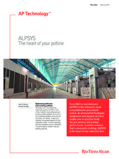
6 The world's first electric Railway in Notes: 1. 2. Statistics include Japanese subways and AGTs. Kazakhstan is 3,528 km (3,000 V dc and 50 Hz 25 kV ac) but details are not known. Lichterfelde marking the first passenger Sources: (1) Railway Electrical Engineering Association of Japan, , , 5, Oct. 1997. electric Railway . (2) Ibid., , , pp. 77 78 and pp. 81 83, Nov. 1997. Electric operation is often preferred on 48 Japan Railway & Transport Review 16 June 1998 Copyright 1998 EJRCF. All rights reserved. Figure 1 History of Railway Electrification in Japan*. 12,000 Electrified Distance History of Electrification Ratio (%). Shinkansen Shinkansen Railway Electrification in Japan JN. R1 AC, Conventional railways 2, km 10,000 0-y DC, Conventional railways ear Commercial operation of electric railways Fin an cia Electrified Distance (km).
7 In Japan dates back to 1895 when a 500- l Re 8,000 str V dc tram system was started in Kyoto. 3r uc dL tur ing Conven- The first electric Railway owned by the on Pla Conventional railways gR n tional an AC electrification Japanese Government railways began op- 60 6,000 ge 3, km railways 2n Pl 9, km an d eration in 1906 between Ochanomizu 5- ye Electrification 1s ar and Nakano in Tokyo, which used to be- t5. 40 4,000 ratio Pl -y an ea long to Kobu railways before being pur- rP. lan chased by the government. The 600-V Conventional railways 20 2,000 nce dc system was later replaced by a 1200- dista DC electrification rified Elect tion ratio 6, km V dc system to prevent voltage drop. In Electrifica 0 0. 1922, it was replaced again by a 1500-V 1906 1940 1945 1950 1955 1960 1965 1970 1975 1980 1985 1990 1995.
8 Dc system when the section between Year Yokohama and Kozu was electrified. The Note: * Including Japanese Government railways , Japanese National railways (JNR, from June 1949. 1500-V dc system is still used Today by to March 1987) and JRs, but excluding private railways all DC electric railways in Japan. The postwar increase in transportation demand in Japan led to the introduction of more powerful electric locomotives Shinkansen in 1972. Today , the AT feed- its own hydroelectric power station in around 1950. At that time, it was feared ing system is the standard for all AC elec- Niigata Prefecture (on the Shinano River). that the 1500-V dc system had reached tric railways in Japan. as well as a thermal power station in its limit, and a study was started on rail- Figure 1 shows the history of Railway elec- Kawasaki City in Kanagawa Prefecture.
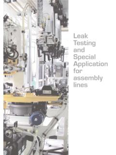
9 Way electrification based on commercial- trification in Japan from the era of the Japa- These two power stations supply the rail- frequency, single-phase alternating nese Government railways until the ways in the Tokyo metropolitan area. current. After a successful demonstration present JRs. Figure 2 maps the various In Japan, the receiving voltage at sub- test on the Senzan Line, the first commer- systems in Japan. Roughly speaking, the stations for direct-current electric railways cial operation using an electric locomo- 1500-V dc system is used on the conven- is usually extra-high tension at 22, 66, or tive started in 1957 on the Senzan and tional railways in Honshu (Kanto, Tokai, 77 kV. This is converted to 1200 V. Hokuriku Lines, soon followed by a 20- Kansai, and Chugoku districts) and by a transformer, and then to direct cur- kV single-phase, alternating-current Shikoku, while the 20-kV ac system is rent by a rectifier at the rated voltage of system using a step up or boosting trans- mainly used in Hokkaido, northern 1500 V (no-load voltage of 1620 V).
10 Sub- former (BT) to minimize inductive inter- Honshu (Tohoku and Hokuriku districts), ways and some private railways use 600. ference in telecommunication lines. and Kyushu. All shinkansen use the 25- or 750 V dc. In 1964, the Tokaido Shinkansen began kV ac system. In contrast, most private The receiving voltage for alternating-cur- operations using the BT feeding system, railways rely on the 1500-V dc system, rent conventional electric railways is an marking the first high-speed train opera- while the 600- or 750-V dc system is used extra-high voltage of 66, 77, 110, or 154. tion with a maximum speed of 210 km/h. by subways and some other railways . kV. The shinkansen use receiving volt- However, it soon faced maintenance and ages of 77, 154, 220, or 275 kV. The con- other technical problems associated with ventional railways use a feeding voltage the large collection current requiring com- Various Feeding Systems of 20 kV, and the shinkansen use single- plex anti-arcing designs.