Transcription of Raspberry Pi Compute Module 3+ Raspberry Pi Compute …
1 DATASHEETR aspberry Pi Compute Module 3+ Raspberry Pi Compute Module 3+ LiteRelease 1, January 2019 Copyright 2019 Raspberry Pi (Trading) Ltd. All rights Module 3+ DatasheetCopyright Raspberry Pi (Trading) Ltd. 2019 Table 1: Release HistoryReleaseDateDescription128/01/2019 First releaseThe latest release of this document can be found 2 Compute Module 3+ DatasheetCopyright Raspberry Pi (Trading) Ltd. 2019 Contents1 Introduction52 ..63 Block Diagram74 Mechanical Specification85 Pin Assignments96 Electrical Specification117 Power Sequencing .. Requirements .. 148 Booting149 .. Alternate Functions .. Memory interface (SMI) .. Parallel interface (DPI) .. interface .. (MIPI serial Camera) .. (MIPI serial Display) .. (TV Out).
2 1910 Temperature Range .. 1911 Availability1912 Support192 Release 2 Compute Module 3+ DatasheetCopyright Raspberry Pi (Trading) Ltd. 2019 List of Figures1CM3+ Block Diagram ..72CM3+ Mechanical Dimensions ..83 Digital IO Characteristics .. 133 Release 2 Compute Module 3+ DatasheetCopyright Raspberry Pi (Trading) Ltd. 2019 List of Tables1 Release History ..12 Compute Module 3+ SODIMM Connector Pinout ..93 Pin Functions .. 104 Absolute Maximum Ratings .. 115DC Characteristics .. 126 Digital I/O Pin AC Characteristics .. 127 Power Supply Operating Ranges .. 138 Mimimum Power Supply Requirements .. 149 GPIO Bank0 Alternate Functions .. 1610 GPIO Bank1 Alternate Functions .. 174 Release 2 Compute Module 3+ DatasheetCopyright Raspberry Pi (Trading) Ltd. 20191 IntroductionThe Raspberry Pi Compute Module 3+ (CM3+) is a range of DDR2-SODIMM-mechanically-compatibleSyste m on Modules (SoMs) containing processor, memory, eMMC Flash (on non-Lite variants) andsupporting power circuitry.
3 These modules allow a designer to leverage the Raspberry Pi hardware andsoftware stack in their own custom systems and form factors. In addition these modules have extra IOinterfaces over and above what is available on the Raspberry Pi model A/B boards, opening up moreoptions for the CM3+ contains a BCM2837B0 processor (as used on the Raspberry Pi 3B+), 1 Gbyte LPDDR2 RAM and eMMC Flash. The CM3+ is currently available in 4 variants, CM3+/8GB, CM3+/16GB,CM3+/32GB and CM3+ Lite, which have 8, 16 and 32 Gigabytes of eMMC Flash, or no eMMC Flash, CM3+ Lite product is the same as CM3+ except the eMMC Flash is not fitted, and the SD/eMMCinterface pins are available for the user to connect their own SD/eMMC that the CM3+ is electrically identical and, with the exception of higher CPU z-height, physicallyidentical to the legacy CM3 + modules require a software/firmware image dated November 2018 or newer to function 2 Compute Module 3+ DatasheetCopyright Raspberry Pi (Trading) Ltd.
4 20192 Hardware Low cost Low power High availability High reliability Tested over millions of Raspberry Pis Produced to date Module IO pins have 15 micro-inch hard gold plating over micron Peripherals 48x GPIO 2x I2C 2x SPI 2x UART 2x SD/SDIO 1x HDMI 1x USB2 HOST/OTG 1x DPI (Parallel RGB Display) 1x NAND interface (SMI) 1x 4-lane CSI Camera interface (up to 1 Gbps per lane) 1x 2-lane CSI Camera interface (up to 1 Gbps per lane) 1x 4-lane DSI Display interface (up to 1 Gbps per lane) 1x 2-lane DSI Display interface (up to 1 Gbps per lane) Software ARMv8 Instruction Set Mature and stable Linux software stack Latest Linux Kernel support Many drivers upstreamed Stable and well supported userland Full availability of GPU functions using standard APIs6 Release 2 Compute Module 3+ DatasheetCopyright Raspberry Pi (Trading) Ltd.
5 20193 Block Diagram1 GByte LPDDR2200 Pin SODIMM ConnectorIO ExpanderCore SMPSGPIO[0:27]GPIO[0:27]VDD_GPIO0-27 VDD_GPIO0-27 GPIO[28:45]GPIO[28:45]VDD_GPIO28-45 VDD_GPIO28-45 VBAT3V33V31V81V8 VDACVDAC4 GByte eMMC(CM3 only)TVDACTVDACCSI CAM0 CSI CAM0 CSI CAM1 CSI CAM12 Lane CSI Camera4 Lane CSI CameraBCM2837B0 DSI DISP0 DSI DISP0 DSI DISP1 DSI DISP12 Lane DSI Display4 Lane DSI DisplayHDMI TMDSCLOCK & DATACMCHOKESRUNHDMI CEC, DDCHDMI CEC, DDCHDMI_HPD_N_1V8 EMMC_EN_N_1V8 JTAGJTAGEMMC_DISABLE_NUSBUSBUSB2 USB_OTGIDUSB_OTGIDHDMI CEC & I2 CSDX_CMD, Dx (CM3+ Lite only)SDX_CLK (CM3+ Lite only)3V3 RUNTVDACGPIOBANK0 GPIOBANK13V3SD_CLKSD_CMD, DxSDX_VDD (CM3+ Lite only)SD I/O VOLTAGE1V8CM3+ eMMC I/O Voltage fixed at 1V8CM3+ Lite SD I/O Voltage supplied from SDX_VDDF igure 1: CM3+ Block Diagram7 Release 2 Compute Module 3+ DatasheetCopyright Raspberry Pi (Trading) Ltd.
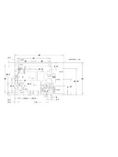
6 20194 Mechanical SpecificationThe CM3+ modules conform to JEDEC MO-224 mechanical specification for 200 pin DDR2 ( )SODIMM modules and therefore should work with the many DDR2 SODIMM sockets available on themarket.(Please note that the pinout of the Compute Module is not the same as a DDR2 SODIMM Module ; they are not electrically compatible.)The SODIMM form factor was chosen as a way to provide the 200 pin connections using a standard,readily available and low cost connector compatible with low cost PCB maximum component height on the underside of the Compute Module is maximum component height on the top side of the Compute Module is Compute Module PCB thickness is +/- that the location and arrangement of components on the Compute Module may change slightlyover time due to revisions for cost and manufacturing considerations; however, maximum componentheights and PCB thickness will be kept as 2 gives the CM3+ mechanical 2: CM3+ Mechanical Dimensions8 Release 2 Compute Module 3+ DatasheetCopyright Raspberry Pi (Trading) Ltd.
7 20195 Pin AssignmentsCM3+CM3+ LitePINPINCM3+CM3+ Lite1234 NCSDX_VDD56 NCSDX_VDD78910 NCSDX_CLK1112 NCSDX_CMD13141516 NCSDX_D01718 NCSDX_D119202122 NCSDX_D22324 NCSDX_D325262728293031323334353637383940 4142434445464748495051525354555657585960 6162636465666768697071727374757677787980 8182838485868788899091929394959697989910 0101102103104105106107108109110111112113 1141151161171181191201211221231241251261 2712812913013113213313413513613713813914 0141142143144145146147148149150151152153 1541551561571581591601611621631641651661 6716816917017117217317417517617717817918 0181182183184185186187188189190191192193 194195196197198199200 KEYEMMC_DISABLE_NGNDGNDGNDGNDGPIO28 GPIO29 GNDGPIO32 GPIO33 GNDGPIO34 GPIO35 GNDGPIO30 GPIO31 GNDGPIO0-27_VDDGPIO28-45_VDDGNDGPIO40 GPIO41 GNDGPIO42 GPIO43 GNDGPIO36 GPIO37 GNDGPIO38 GPIO39 GNDDSI1_DP0 DSI1_DN0 GNDDSI1_CPDSI1_CNGNDGPIO44 GPIO45 GNDGNDDSI1_DP1 DSI1_DN1 GNDNCNCNCDSI1_DP3 DSI1_DN3 GNDDSI1_DP2 DSI1_DN2 GNDCAM0_DP1 CAM0_DN1 GNDNCNCGNDCAM0_DP0 CAM0_DN0 GNDGNDVBATVBATVC_TDOVC_TCKGND1V81V8 GNDGNDGPIO0 GPIO1 GNDGPIO2 GPIO3 VDAC3V33V3 TVDACUSB_OTGIDGNDVC_TRST_NVC_TDIVC_TMSNC NCNCNCNCGNDCAM0_CPCAM0_CNGNDGNDGPIO8 GPIO9 GNDGPIO10 GPIO11 GNDGPIO4 GPIO5 GNDGPIO6 GPIO7 GPIO13 GNDGPIO14 GPIO15 GNDGPIO16 GNDGPIO0-27_VDDGPIO28-45_VDDGNDGPIO12 GPIO21 GNDGPIO22 GPIO23 GNDGPIO24 GPIO17 GNDGPIO18 GPIO19 GNDGPIO20 DSI0_DP1 GNDDSI0_DN0 DSI0_DP0 GNDDSI0_CNGPIO25 GNDGPIO26 GPIO27 GNDDSI0_DN1 HDMI_D0_PGNDHDMI_D1_NHDMI_D1_PGNDHDMI_D2 _NDSI0_CPGNDHDMI_CLK_NHDMI_CLK_PGNDHDMI_ D0_NUSB_DPCAM1_DN2 GNDCAM1_CPCAM1_CNGNDCAM1_DP1 HDMI_D2_PGNDCAM1_DP3 CAM1_DN3 GNDCAM1_DP23V33V3 GNDVBATVBATHDMI_HPD_N_1V8
8 EMMC_EN_N_1V8 VDD_CORE (DO NOT CONNECT)GND1V81V8 GNDVDACUSB_DMGNDHDMI_CECHDMI_SDAHDMI_SCL RUNCAM1_DN1 GNDCAM1_DP0 CAM1_DN0 GNDT able 2: Compute Module 3+ SODIMM Connector PinoutTable 2 gives the Compute Module 3+ pinout and Table 3 gives the pin 2 Compute Module 3+ DatasheetCopyright Raspberry Pi (Trading) Ltd. 2019 Pin NameDIRV oltage RefPDNaStateIf UnusedDescription/NotesRUN and Boot Control (see text for usage guide)RUNI3V3bPull HighLeave openHas internal 10k pull upEMMCDISABLENI3V3bPull HighLeave openHas internal 10k pull upEMMCENN1V8O1V8 Pull HighLeave openHas internal 2k2 pull upGPIOGPIO[27:0]I/OGPIO0-27 VDDPull or Hi-ZcLeave openGPIO Bank 0 GPIO[45:28]I/OGPIO28-45 VDDPull or Hi-ZcLeave openGPIO Bank 1 Primary SD Interfaced,eSDXCLKOSDXVDDPull HighLeave openPrimary SD interface CLKSDXCMDI/OSDXVDDPull HighLeave openPrimary SD interface CMDSDXDxI/OSDXVDDPull HighLeave openPrimary SD interface DATAUSB InterfaceUSBDxI/O-ZLeave openSerial interfaceUSBOTGIDI3V3 Tie to GNDOTG pin detectHDMI InterfaceHDMISCLI/O3V3bZfLeave openDDC Clock ( tolerant)HDMISDAI/O3V3bZfLeave openDDC Data ( tolerant)HDMICECI/O3V3 ZLeave openCEC (has internal 27k pull up)HDMICLKxO-ZLeave openHDMI serial clockHDMIDxO-ZLeave openHDMI serial dataHDMIHPDN1V8I1V8 Pull HighLeave openHDMI hotplug detectCAM0 (CSI0) 2-lane InterfaceCAM0 CxI-ZLeave openSerial clockCAM0 DxI-ZLeave openSerial dataCAM1 (CSI1)
9 4-lane InterfaceCAM1 CxI-ZLeave openSerial clockCAM1 DxI-ZLeave openSerial dataDSI0 (Display 0) 2-lane InterfaceDSI0 CxO-ZLeave openSerial clockDSI0 DxO-ZLeave openSerial dataDSI1 (Display 1) 4-lane InterfaceDSI1 CxO-ZLeave openSerial clockDSI1 DxO-ZLeave openSerial dataTV OutTVDACO-ZLeave openComposite video DAC outputJTAG InterfaceTMSI3V3 ZLeave openHas internal 50k pull upTRSTNI3V3 ZLeave openHas internal 50k pull upTCKI3V3 ZLeave openHas internal 50k pull upTDII3V3 ZLeave openHas internal 50k pull upTDOO3V3 OLeave openHas internal 50k pull upaThe PDN column indicates power-down state (when RUN pin LOW)bMust be driven by an open-collector drivercGPIO have software enabled pulls which keep state over power-downdOnly available on Lite variantseThe CM will always try to boot from this interface firstfRequires external pull-up resistor to 5V as per HDMI specTable 3: Pin Functions10 Release 2 Compute Module 3+ DatasheetCopyright Raspberry Pi (Trading) Ltd.
10 20196 Electrical SpecificationCaution!Stresses above those listed in Table 4 may cause permanent damage to the device. This isa stress rating only; functional operation of the device under these or any other conditions above thoselisted in the operational sections of this specification is not implied. Exposure to absolute maximumrating conditions for extended periods may affect device SMPS Supply Supply DAC I/O Supply I/O Supply SD/eMMC Supply 4: Absolute Maximum RatingsDC Characteristics are defined in Table 511 Release 2 Compute Module 3+ DatasheetCopyright Raspberry Pi (Trading) Ltd. 2019 SymbolParameterConditionsMinimumTypicalM aximumUnitVILI nput low voltageaVDDIO = = = high voltageaVDDIO = = = leakage currentTA = +85 C--5 ACINI nput capacitance--5-pFVOLO utput low voltagebVDDIO = , IOL = = , IOL = = , IOL = high voltagebVDDIO = , IOH = = , IOH = = , IOH = low currentcVDDIO = , VO = = , VO = = , VO = high currentcVDDIO = , VO = = , VO = = , VO = UPullup resistor-50-65k RP DPulldown resistor-50-65k aHysteresis enabledbDefault drive strength (8mA)cMaximum drive strength (16mA)Table 5: DC CharacteristicsAC Characteristics are defined in Table 6 and Fig.