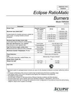
Transcription of Reference: NFPA 86 – Ovens and Furnaces, 1999 …
1 The scope of NFPA 86 extends to all the factors involved in the safe operation of Ovens and furnaces, andanyone designing or building them should be familiar with the entire standard. Copies can be purchased from:The National Fire Protection Association1 Batterymarch ParkQuincy, MA 02269-9101800-344-3555508-895-8300 if outside Section 2 Sheet R-1 NFPA Requirements for Gas Burner SystemsReference: NFPA 86 Ovens and Furnaces, 1999 EditionGeneral Remarks:The schematic and notes on the following page condense the gas burner system requirements of National FireProtection Association (NFPA) 86 into an easy-to-use format. They should provide most of the engineeringinformation required to lay out burner air and gas trains. Numbers in parentheses refer to the applicableparagraphs of the addition to the requirements shown on the schematic, NFPA 86 also requires that the combustion controlsystem have the following features:1)Safety control circuits must be single phase, one side grounded, with all breaking contacts in the hot , ungrounded, circuit protected line not exceeding 120V.
2 ( )2)Prior to energizing spark or lighting pilot, a timed pre-purge of at least four standard cubic feet of airper cubic foot of heating chamber volume is required ( ).a)Airflow must be proven & maintained during the )Safety shutoff valve must be closed and when the chamber input exceeds 400,000 Btu/hr(117 kW) it must be proved and )Exceptions to a re-purge are allowed for momentary shutdowns if (any one): ( )a)Each burner is supervised, each has safety shutoff valves, and the fuel accumulation in theheating chamber can not exceed 25% of lower explosive )Each burner is supervised, each has safety shutoff valves, and at least one burner remains on insame )The chamber temperature is more than 1400 F (760 C).4)Exception to the pre-purge is allowed for explosion resistant radiant tube systems.
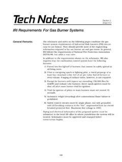
3 ( )5)All safety interlocks must be connected in series ahead of the safety shutoff valves. Interposingrelays are allowed when the required load exceeds the rating of available safety contacts or wheresafety logic requires separate inputs, AND the contact goes to a safe state on loss of power, ANDeach relay serves only one interlock. ( )6)Any motor starters required for combustion must be interlocked into the safety circuit. ( )7)A listed manual reset excess temperature limit control is required except where the system designcan not exceed the maximum safe temperature. (5-16)8)The user has the responsibility for establishing a program of inspection, testing, and maintenancewith documentation performed at least annually. ( )103 Gas FlowControlsAir FlowControls 1234561179981012131415168 Gas*Underwriters Laboratory (UL) listing is accepted throughout the United States.
4 Listed products can be found in the UL Gas and OilEquipment Directory, available from Underwriters Laboratory, Inc. Publications Stock, 333 Pfingsten Road, Northbrook, IL Mutual (FM) listed equipment is also acceptable in most jurisdictions and can be found in the FM Approval Guide available fromFactory Mutual Research Corporation, 115 Boston-Providence Turnpike, Norwood, MA to install drip leg or sediment trap for each fuel supply line. Must be a minimum of 3 manual shutoff valve to each piece of equipment. 1/4 turn valves or strainer to protect downstream safety shutoff regulator required wherever plant supply pressure exceeds level required for proper burner functionor is subject to excessive vent to safe location outside the building with water protection & bug screen.
5 Vent piping can terminate inside the building when gas is lighter than air, vent contains restricted orifice, and there is sufficient building ventilation. Vent piping not required for lighter than air gases at less than 1 psi, vent contains restricted orifice, and there is sufficient ventilation. Vent piping not required for ratio pressure switches may be vented to regulator vent lines if backloading won t valve required if gas pressure at regulator inlet exceeds rating of safety shutoff listed* safety shutoff valves required for each main and pilot gas burner system. A single valve can beused for explosion resistant radiant tube indication (not proof-of-closure) required on safety shutoff valves to burners or pilots in excess of150,000 Btu/hr (44 kW).
6 10 For capacities over 400,000 Btu/hr (117 kW) at least one safety shutoff valve must have a closed positionswitch to interlock with the and ready means for checking leak tightness of safety shutoff * low gas pressure switch (normally open, makes on pressure rise).13 Listed* high gas pressure switch (normally closed, breaks on pressure rise).14 Flame Supervision: Piloted burners- Continuous pilot: Two flame sensors must be used, one for the pilot flame and one for the main burner Intermittant pilot: Can use a single flame sensor for self-piloted burners (from same port as main, orhas a common flame base and has a common flame envelope with the main flame).- Interrupted pilot: A single flame sensor is allowed. Line, Pipe, Radiant burners- If the burners are adjacent and light safely and reliably from burner to burner, then a single sensor is allowed if it is located at the farthest end from the source of Ignition: Except for explosion resistant radiant tube systems, direct spark igniters must be shut off after main burner trial-for-ignition.
7 If a burner must be ignited at reduced input (forced low fire start), an ignition interlock must be provided to prove control valve position. Trial-for-ignition of the pilot or main must not exceed 15 seconds. An exception is allowed where fuel accumulation in the heating chamber can not exceed 25% of the lower explosive limit and the authority having jurisdiction approves a written request for extended * combustion air flow or pressure proving switch (normally open, makes on pressure rise).