Transcription of Reinforced Concrete Design CHAPTER SHEAR IN BEAMS
1 1 A. J. Clark School of Engineering Department of Civil and Environmental EngineeringFifth EditionCHAPTER4aReinforced Concrete DesignENCE 355 - Introduction to Structural DesignDepartment of Civil and Environmental EngineeringUniversity of Maryland, College ParkSHEAR IN BEAMSPart I Concrete Design and AnalysisFALL 2002 ByDr . Ibrahim. AssakkafCHAPTER 4a. SHEAR IN BEAMSS lide No. 1 ENCE 355 AssakkafIntroductionQThe previous chapters dealt with the flexural strength of must also have an adequate safety margin against other types of failure such as SHEAR , which may be more dangerous than flexural SHEAR forces create additional tensile stresses that must be 4a. SHEAR IN BEAMSS lide No. 2 ENCE 355 AssakkafIntroductionQShear Failure SHEAR failure of Reinforced Concrete beam, more properly called diagonal tension failure , is difficult to predict accurately.
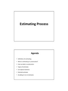
2 In spite of many years of experimental research and the use of highly sophisticated computational tools, it is not fully understood. If a beam without properly designed for SHEAR reinforcement is overloaded to failure, SHEAR collapse is likely to occur 4a. SHEAR IN BEAMSS lide No. 3 ENCE 355 AssakkafIntroductionFigure 1. SHEAR Failure (Nilson, 1997)(a) Overall view, (b) detail near right 4a. SHEAR IN BEAMSS lide No. 4 ENCE 355 AssakkafIntroductionQShear Failure (cont d) Figure 1 shows a SHEAR -critical beam tested under point loading. With no SHEAR reinforcement provided, the member failed immediately upon formation of the critical crack in the high- SHEAR region near the right 4a. SHEAR IN BEAMSS lide No. 5 ENCE 355 AssakkafIntroductionQShear Failure (cont d)When are the shearing effects so large thatthey cannot be ignored as a designconsideration?
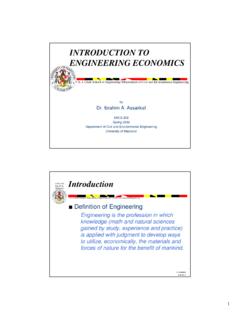
3 It is somehow difficult to answer this question. Probably the best way to begin answering this question is to try to approximate the SHEAR stresses on the cross section of the 4a. SHEAR IN BEAMSS lide No. 6 ENCE 355 AssakkafIntroductionQShear Failure (cont d) Suppose that a beam is constructed by stacking several slabs or planks on top of another without fastening them together. Also suppose this beam is loaded in a direction normal to the surface of these slabs. When a bending load is applied, the stack will deform as shown in Fig. 2a. Since the slabs were free to slide on one one another, the ends do not remain even but 4a. SHEAR IN BEAMSS lide No. 7 ENCE 355 AssakkafIntroductionQShear Failure (cont d)PFigure 2a(a) Unloaded Stack of Slabs(b) Unglued Slabs loaded5 CHAPTER 4a. SHEAR IN BEAMSS lide No. 8 ENCE 355 AssakkafIntroductionQShear Failure (cont d) Each of the slabs behaves as independent beam, and the total resistance to bending of n slabs is approximately n times the resistance of one slab alone.
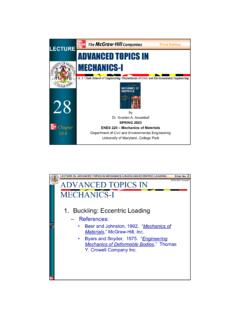
4 If the slabs of Fig. 2b is fastened or glued, then the staggering or relative longitudinal movement of slabs would disappear under the action of the force. However, SHEAR forces will develop between the slabs. In this case, the stack of slabs will act as a solid 4a. SHEAR IN BEAMSS lide No. 9 ENCE 355 AssakkafIntroductionQShear Failure (cont d)PFigure 2b(c) Glued Slabs Unloaded(d) Glued Slabs loaded6 CHAPTER 4a. SHEAR IN BEAMSS lide No. 10 ENCE 355 AssakkafIntroductionQShear Failure (cont d) The fact that this solid beam does not exhibit this relative movement of longitudinal elements after the slabs are glued indicates the presence of shearing stresseson longitudinal planes. Evaluation of these shearing stresses will be discussed in the next couple of 4a. SHEAR IN BEAMSS lide No. 11 ENCE 355 AssakkafIntroductionQTheoretical Background The concept of stresses acting in homogeneous BEAMS are usually covered in various textbooks of mechanics of materials (strength of materials).
5 It can be shown that when the material is elastic, SHEAR stresses can be computed fromIbVQv=v= SHEAR stress Q= statical moment of area about external SHEAR force b= width of the cross sectionI= moment of inertia about neutral axis(1)7 CHAPTER 4a. SHEAR IN BEAMSS lide No. 12 ENCE 355 AssakkafIntroductionQTheoretical Background Also, when the material is elastic, bending stresses can be computed fromIMcf=f= bending stressM= external or applied momentc= the distance from the neutral axis to out fiber ofthe cross sectionI= moment of inertia of the cross section about (2) CHAPTER 4a. SHEAR IN BEAMSS lide No. 13 ENCE 355 AssakkafIntroductionQTheoretical Background All points in the length of the beam, where the SHEAR and bending moment are not zero, and at locations other than the extreme fiber or neutral axis, are subject to both shearing stresses and bending stresses.
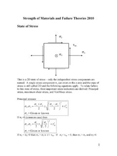
6 The combination of these stresses produces maximum normal and shearing stresses in a specific plane inclined with respect to the axis of the beam. 8 CHAPTER 4a. SHEAR IN BEAMSS lide No. 14 ENCE 355 AssakkafIntroductionQTheoretical Background The distributions of the bending and SHEAR stresses acting individually are shown in Figs. 3, 4, 5, and axisCentroidal axisccFigure 3. Bending StressIMcf= CHAPTER 4a. SHEAR IN BEAMSS lide No. 15 ENCE 355 AssakkafIntroductionQTheoretical BackgroundFigure 4. Bending StressIMcf=9 CHAPTER 4a. SHEAR IN BEAMSS lide No. 16 ENCE 355 AssakkafIntroductionQTheoretical BackgroundFigure 5. Vertical Shearing Stress StressIbVQv= CHAPTER 4a. SHEAR IN BEAMSS lide No. 17 ENCE 355 AssakkafIntroductionQTheoretical BackgroundFigure 6. Vertical Shearing StressIbVQv=10 CHAPTER 4a. SHEAR IN BEAMSS lide No. 18 ENCE 355 AssakkafIntroductionQPrincipal Planes The combination of bending moment and shearing stresses is of such a nature that maximum normal and shearing shearing stresses at a point in a beam exist on planes that are inclined with the axis of the beam.
7 These planes are commonly called principal planes, and the stresses that act on them are referred to as principal 4a. SHEAR IN BEAMSS lide No. 19 ENCE 355 AssakkafIntroductionQPrincipal Planes Plane State of Stressyx y yz xy xz zx zy x z y xy x x y xy yx 11 CHAPTER 4a. SHEAR IN BEAMSS lide No. 20 ENCE 355 AssakkafIntroductionQPrincipal Planes Plane State of StressComponents:Normal Stress xNormal Stress yShearing Stress xyShearing Stress yxy yx xy x x y xy yx yxxy = AACHAPTER 4a. SHEAR IN BEAMSS lide No. 21 ENCE 355 AssakkafIntroductionQPrincipal Stresses The principal stresses in a beam subjected to SHEAR and bending may be computed using the following equation:2242vfffpr+ =(3)fpr= principal stressf= bending stress computed from Eq. 2v= shearing stress computed from Eq. 112 CHAPTER 4a. SHEAR IN BEAMSS lide No. 22 ENCE 355 AssakkafIntroductionQOrientation Principal Planes The orientation of the principal planes may be calculated using the following equation: Note that at the neutral axis of the beam, the principal stresses will occur at a 450angle.
8 = fv2tan211 (4) CHAPTER 4a. SHEAR IN BEAMSS lide No. 23 ENCE 355 AssakkafIntroductionQState of Stress at the Neutral Axis of a Homogeneous 7. SHEAR Stress Relationship(a) Beam under Uniform Loading(b) Stresses on Unit Elementw13 CHAPTER 4a. SHEAR IN BEAMSS lide No. 24 ENCE 355 AssakkafIntroductionQState of Stress at the Neutral Axis of a Homogeneous Beam Diagonal TensionvyxvxyvyxvxyvyxvxyvyxvxyABCDF igure 8 This plane is subjectto compressionThis plane is subjectto tensionCHAPTER 4a. SHEAR IN BEAMSS lide No. 25 ENCE 355 AssakkafIntroductionQState of Stress at the Neutral Axis of a Homogeneous Beam Diagonal Tension Plane A-B is subjected to compression While Plane C-D is subjected to tension. The tension in Plane C-D is historically called diagonal tension . Note that Concrete is strong in compression but weak in tension, and there is a tendency for Concrete to crack on the plane subject to tension.
9 When the tensile stresses are so high, it is necessary to provide 4a. SHEAR IN BEAMSS lide No. 26 ENCE 355 AssakkafIntroductionQDiagonal Tension Failure In the BEAMS with which we are concerned, where the length over which a SHEAR failure could occur (the SHEAR span) is in excess of approximately three times the effective depth, the diagonal tension failure would be the mode of failure in SHEAR . Such a failure is shown in Figs. 1 and 8. For longer SHEAR spans in plain Concrete BEAMS , cracks due to flexural tensile stresses would occur long before cracks due to diagonal 4a. SHEAR IN BEAMSS lide No. 27 ENCE 355 AssakkafIntroductionQDiagonal Tension FailureFigure 8. Typical Diagonal Tension FailureShear SpanPortion of span in whichShear stress is high15 CHAPTER 4a. SHEAR IN BEAMSS lide No. 28 ENCE 355 AssakkafIntroductionFigure 1. SHEAR Failure (Nilson, 1997)(a) Overall view, (b) detail near right 4a.
10 SHEAR IN BEAMSS lide No. 29 ENCE 355 AssakkafIntroductionQBasis of ACI Design for SHEAR The ACI provides Design guidelines for SHEAR reinforcement based on the vertical SHEAR force Vuthat develops at any given cross section of a member. Although it is really the diagonal tension for which SHEAR reinforcing must be provided, diagonal tensile forces (or stresses) are not calculated. Traditionally, vertical SHEAR force has been taken to be good indicator of diagonal tension 4a. SHEAR IN BEAMSS lide No. 30 ENCE 355 AssakkafShear Reinforcement Design RequirementsQWeb Reinforcement The basic rationale for the Design of the SHEAR reinforcement, or web reinforcement as it usually called in BEAMS , is to provide steel to cross the diagonal tension cracks and subsequently keep them from opening. In reference to Fig. 8, it is seen that the web reinforcement may take several forms such as: CHAPTER 4a.