Transcription of Relays & Sockets - IDEC
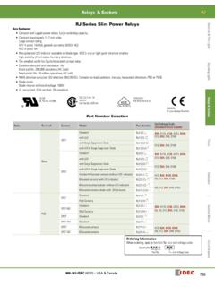
1 Relays & Sockets RR. RR Series Power Relays Switches & Pilot Lights Key features: SPDT through 3 PDT, 10A contacts Midget power type Relays Available in pin and blade terminal styles. Options include an indicator, check button for test operations and side flange. DIN rail, surface and panel mount Sockets are available for a wide a variety of mounting applications. Signaling Lights Part Number Selection Part Number Coil Voltage Code Contact Model Pin Terminal Blade Terminal*. (Standard Stock Items in Bold). SPDT Standard RR1BA-U 0. Relays & Sockets With Indicator RR1BA-UL 0. With Check Button RR1BA-UC 0. With Indicator and Check Button RR1BA-ULC 0. Side Flange Model RR1BA-US 0. DPDT Standard RR2P-U 0 RR2BA-U 0. With Indicator RR2P-UL 0 RR2BA-UL 0. AC6V, AC12V, AC24V, AC110V, AC120V, With Check Button RR2P-UC 0 RR2BA-UC 0 AC240V, With Indicator and Check Button DC6V, DC12V, DC24V, DC48V, DC110V.
2 RR2P-ULC 0 RR2BA-ULC 0. Timers Side Flange Model RR2BA-US 0. 3 PDT Standard RR3PA-U 0 RR3B-U 0. With Indicator RR3PA-UL 0 RR3B-UL 0. With Check Button RR3PA-UC 0 RR3B-UC 0. With Indicator and Check Button RR3PA-ULC 0 RR3B-ULC 0. Side Flange Model RR3B-US 0. Contactors *Blade type not TUV tested or CE marked. Side flange model mounts directly to panel with no socket required. Ordering Information When ordering, specify the Part No. and coil voltage code: (example) RR3B-U AC120V. Part No. Coil Voltage Code Sockets Relays Standard DIN Rail Mount Finger-safe DIN Rail Mount Through Panel Mount Terminal Blocks SR2P-05. RR2P SR2P-05C SR2P-51. SR2P-06. SR3P-05. RR3PA SR3P-05C SR3P-51. SR3P-06. RR1BA. RR2BA SR3B-05 SR3B-51. RR3B. Circuit Breakers All DIN rail mount Sockets shown above can be mounted using DIN rail BNDN1000.
3 800-262-IDEC (4332) USA & Canada 783. RR Relays & Sockets Hold Down Springs & Clips Switches & Pilot Lights For DIN For Through Panel &. Appearance Description Relay Mount Socket PCB Mount Socket RR2P SR2B-02F1. SR3P-01F1. Pullover Wire RR3PA SR3B-02F1. Spring RR1BA, RR2BA, SR3B-02F1 SR3B-02F1. RR3B. Leaf Spring RR2P, RR3PA SFA-203 . (side latch). Signaling Lights Accessories Item Appearance Use with Part No. Remarks The BNDN1000 is designed to accommodate DIN mount Sockets . Aluminum Made of durable extruded aluminum, the BNDN1000 measures DIN Rail All DIN rail Sockets BNDN1000. ( ) in height and (35mm) in width (DIN standard). Standard (1 meter length). length is 39 (1,000mm). Relays & Sockets DIN Rail End DIN rail BNL5 mm wide. Stop Horseshoe clip for Sockets Y778-011. Replacement SR3B-05, SR2P-06, SR3P-06.
4 For use on DIN rail mount socket when using pullover wire hold down Hold-Down spring. 2 pieces included with each socket. Spring Anchor Chair clip for Sockets Y703-102. SR2P-05(C), SR3P-05(C). Timers Contactors Terminal Blocks Circuit Breakers 784 Relays & Sockets RR. Specifications Switches & Pilot Lights Contact Material Silver Contact Resistance 1 30 m maximum Minimum Applicable Load 1V DC, 10 mA. Operating Time 2. 25 ms maximum Release Time 2. 25 ms maximum AC: 3 VA (50 Hz), VA (60 Hz). Power Consumption (approx.). DC: Insulation Resistance 100 M minimum (500V DC megger). Signaling Lights Between live and dead parts: 1500V AC, 1 minute Between contact and coil: 1500V AC, 1 minute Pin Terminal Between contacts of different poles: 1500V AC, 1 minute Dielectric Between contacts of the same pole: 1000V AC, 1 minute Strength Between live and dead parts: 2000V AC, 1 minute 1.
5 Measured using 5V DC, 1A voltage drop method 2. Measured at the rated voltage (at 20 C), excluding contact Between contact and coil: 2000V AC, 1 minute bouncing Blade Terminal 3. For use under different temperature conditions, refer to Between contacts of different poles: 2000V AC, 1 minute Continuous Load Current vs. Operating Temperature Curve. Relays & Sockets Between contacts of the same pole: 1000V AC, 1 minute Electrical: 1800 operations/h maximum Operating Frequency Mechanical: 18,000 operations/h maximum Damage limits: 10 to 55 Hz, amplitude mm Vibration Resistance Operating extremes: 10 to 55 Hz, amplitude mm Damage limits: 1000 m/s2 (100g). Shock Resistance Operating extremes: 100 m/s2 (10G). Mechanical Life 10,000,000 operations Electrical Life 200,000 operations (220V AC, 5A). Timers Operating Temperature 3.
6 25 to +40 C (no freezing). Operating Humidity 5 to 85% RH (no condensation). Weight (approx.) (Standard type) RR2P: 90g, RR3PA: 96g, RR1BA/RR2BA/RR3B: 82g Coil Ratings Rated Current (mA) 15% (at 20 C) Operating Characteristics (values at 20 C). Coil Resistance ( ). Rated Voltage (V) Maximum Continuous 50 Hz 60 Hz 10% (at 20 C) Pickup Voltage Dropout Voltage Contactors Applied Voltage 6 490 420 12 245 210 18. AC 24 121 105 79. 110% 80% maximum 30% minimum (50/60 Hz) 110 27 23 1,680. 120 24 2,100. 240 8,330. Terminal Blocks 6 240 25. 12 120 100. DC 24 60 400 110% 80% maximum 10% minimum 48 30 1,600. 110 13 8,460. Circuit Breakers 800-262-IDEC (4332) USA & Canada 785. RR Relays & Sockets Contact Ratings UL Ratings Switches & Pilot Lights Maximum Contact Capacity Voltage Resistive General use Horse Power Rating Allowable Contact Power Rated Load 240V AC 10A 7A 1/3 HP.
7 Continuous Current Resistive Inductive 120V AC 10A 1/4 HP. Voltage (V) Res. Load Ind. Load Load Load 30V DC 10A 7A . 110 AC 10A 1650VA AC 1100VA AC CSA Ratings 10A 220 AC 5A. 300W DC 150W DC. 30 DC 10A 5A Voltage Resistive General use 240V AC 10A 7A. Note: Inductive load for the rated load cos = , L/R = 7 ms Signaling Lights 120V AC 10A 100V DC T V Ratings 30V DC 10A Voltage 240V AC 10A. AC: cos = , DC: L/R = 0 ms 30V DC 10A. Relays & Sockets Socket Specifications Relays Terminal Electrical Rating Wire Size Torque SR2P-05 M3 screw with captive wire clamp 300V, 10A Maximum 2 - #12 AWG 9 - lbs SR2P-05C M3 screw with captive wire clamp, fingersafe 300V, 10A Maximum 2 - #12 AWG 9 - lbs SR2P-06 M3 screw with captive wire clamp 300V, 10A Maximum 2 - #12 AWG 9 - lbs DIN Rail SR3P-05 M3 screw with captive wire clamp 300V, 10A Maximum 2 - #12 AWG 9 - lbs Sockets SR3P-05C M3 screw with captive wire clamp, fingersafe 300V, 10A Maximum 2 - #12 AWG 9 - lbs SR3P-06 M3 screw with captive wire clamp 300V, 10A Maximum 2 - #12 AWG 9 - lbs Timers SR3B-05 M3 screw with captive wire clamp 300V, 15A (10A)* (*CSA rating) Maximum 2 - #12 AWG 9 - lbs SR2P-51 Solder 300V, 10A.
8 Through Panel Mount SR3P-51 Solder 300V, 10A . Sockets SR3B-51 Solder 300V, 10A . Contactors Terminal Blocks Circuit Breakers 786 Relays & Sockets RR. Characteristics (Reference Data). Switches & Pilot Lights Electrical Life Curves AC Load DC Load 1000 1000. 500 500. 30V DC. Life ( 10,000 operations). resistive Life ( 10,000 operations). 100 100. 110V AC resistive 100V DC resistive 50 50. Signaling Lights 220V AC resistive 110V AC inductive 100V DC inductive 20 20. 220V AC inductive 30V DC inductive 10 10. 1 5 10 1 5 10. Load Current (A) Load Current (A). Continuous Load Current vs. Operating Temperature Curve Maximum Switching Capacity (Standard Type, With Check Button, and Side Flange Type). AC. resistive 100. Relays & Sockets 90. AC. inductive 80. Operating Temperature (C). DC resistive 70. Load Current (A).
9 DC Coil 60. DC inductive 50. AC Coil 40. 30. 20. 10. 1 5 10 30 50 100 200 300 0. 1 2 3 4 5 6 7 8 9 10. Load Voltage (V) Load Current (A). Timers Internal Connection (View from Bottom). Standard Type RR2P-U RR3PA-U RR1BA-U RR2BA-U RR3B-U With Check Button Front Pushbutton Contacts can be operated by pressing the Contactors check button. With Indicator (-UL type). RR2P RR3PA RR1BA RR2BA RR3B. Terminal Blocks Coil Below 100V When the relay is energized, AC/DC the indicator goes on. An LED protection diode is not contained in relay coils below 100V DC. Coils below 100V use LED indicator while coils above 100V use neon lamp Coil Circuit Breakers indicator. 100V. AC/DC. and over 800-262-IDEC (4332) USA & Canada 787. RR Relays & Sockets Dimensions (mm). Switches & Pilot Lights RR2P-U/RR2P-UL RR3PA-U/RR3PA-UL.
10 Total length from panel surface including relay socket Total length from panel surface including relay socket SR2P-05: ( ) max., SR2P-511: 63 (68) max. SR3P-05: ( ) max., SR3P-511: 63 (68) max. 6. 5 7. 4 5 4 8. 3 6. 2 7 3 9. 1 8. 2 10. 1 11. Signaling Lights max. 13 max. 13. Dimensions in the ( ) Dimensions in the ( ). include a hold-down spring. include a hold-down spring. RR1BA-U/RR2BA-UL/RR2BA-U. RR2BA-UL/RR3B-U/RR3B-UL RR1BA-US/RR2BA-US/RR3B-US. oblong hole 2- Mounting Holes Relays & Sockets oblong hole Total length from panel surface including relay socket SR3B-05: 73 (76) max., SR3B-51: 56 (60) max. max. 1 2 3. 4 5 6. 7 8 9. 36. 1 2 3. 4 5 6. A B. 7 8 9. 36. 36 A B. max. Dimensions in the ( ) 36. include a hold-down spring. Timers Standard DIN Rail Mount Sockets SR2P-05 SR2P-06. 36 DIN Rail 40.