Transcription of Reliance Installation and Operating Instructions
1 Installation AND Operating Instructions 0 Q-Series MANUAL TRANSFER SWITCHES FROM Residential Wattage Requirements Appliance Running Watts Add watts for starting Furnace blower, gas or fuel 1/8 hp300 500 1/8 hp500 750 1/6 hp500 750 1/4 hp600 1000 1/3 hp700 1400 1/2 hp875 2100 Shallow well pump 1/3 hp750 1400 1/2 hp1000 2350 Sump pump 1/3 hp800 1300 1/2 hp1050 2150 Refrigerator or freezer 800 2300 Garage door opener 1/4 hp550 1100 1/3 hp750 1400 Lights on bulb 0 Radio 50-200 0 Television 100-300
2 0 Microwave oven 600-1500 0 Coffee maker, typical 1750 0 Toaster/toaster oven 1050-18500 Portable heater 1100-15000 Dehumidifier 650-800 0 Electric blanket 400 0 Clothes washer 1150 2300 Clothes dryer, gas 700 1800 Dishwasher cool dry700 1400 hot dry1450 1400 Vacuum cleaner 800-1100 0 Hair dryer 300-1500 0 Iron 1200 0 1 Warnings Cautions 1 Warning: Improper Installation of this transfer switch could cause damage or personal injury by electrocution or fire.
3 Installation must be performed by a qualified electrician in compliance with all applicable electrical codes Caution: Reliance transfer switches covered in this manual should not be used for appliances or systems that may exceed the capacity of the product. Caution: When the transfer switch is connected to branch circuits with AFCI or GFCI breakers, the AFCI or GFCI protection will be lost when, and only when, the toggle switch in the transfer switch is in the GEN position. To get AFCI or GFCI protection when running on generator power, it must be provided at the outlet(s). Reliance Controls Corporation is not responsible for damage or injury caused by incorrect Installation of this transfer switch.
4 Member, National Electrical Manufacturers Association Reliance Installation and Operating Instructions Key Components of the Reliance Transfer Switch 2 Handle tie Circuit breakers. Each transfer switch circuit has a 1-in interchangeable circuit breaker that protects the branch circuit when the circuit selector switch is in the GEN position. In the LINE position, each branch circuit is protected by the breaker in the load center. Circuit selector switches. These switches allow you to select either GEN (generator) or LINE (utility) as the power source for the branch circuits that have been wired through the transfer switch.
5 The OFF position is generally not used, as a switch in the OFF position removes that branch circuit from both utility and generator power. Handle ties. Handle ties are used for 240-volt circuits or multi-wire branch circuits. They may be removed for 120-volt circuits. See page 6 for Instructions on removing and adding handle ties. Power inlet (selected models only). The power cord from the generator is plugged into this inlet. Not needed for hard-wire Installation with remote power inlet box. Power inlet filler plate. Models without the power inlet installed have a filler plate covering the hole in the wiring compartment cover.
6 This can be replaced with a power inlet. Models with a power inlet installed have a filler plate included in the unit carton. This can replace the power inlet for hard-wire Installation . Wiring Compartment Cover. All models include a wiring compartment that can be used to hard-wire the unit to a remote power inlet box. Analog wattmeters (suffix -A and -C models). These meters indicate the total load, in watts, on each side of the generator when the generator is supplying power as follows: The left meter measures the load on The right meter measures the load on A, C, and E 6-circuit B, D and F 6-circuitA, C, E, G and I 10-circuit B, D, F, H and J 10-circuitNote: The watt meters will register only if power is being used from the generator.
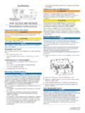
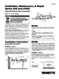
7 Power Inlet (cord-connected models only) Figure 1 Circuit Selector Switches Circuit Breakers Watt meters (select models only) Wiring Compartment Cover Circuit Breaker Compartment CoverElectronic wattmeter (suffix -AE and -CE models). Two sets of LED readouts (a long and a short) appear on the face of the meter. The left set applies to the circuits shown in the left box above, with the longer scale indicating the total wattage supplied from the generator to those circuits, and the shorter scale indicating the relative generator output voltage on those circuits. In a similar manner, the right set applies to those circuits shown in the right box above.
8 A green readout indicates that voltage and amperage are within an acceptable range. In addition, a mains on indicator appears in the upper left corner, and will be lit when utility power is available and the main circuit breaker in the load center is in the on position. The generator must also be connected and running for the mains on indicator to operate properly. Installation Instructions Preparing for Installation You will need the following items: Electric drill Screwdriver Wire cutters/stripper Hammer Four anchors and screws 6 or 10 yellow wire connectors (depending on the model) 4 red wire connectors for the 20A and 30A hard-wire models The following five steps generally apply to all transfer switch installations.
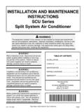
9 The transfer switch may be installed on either side of the load center. 1. Turn off the main circuit breaker in the load center to ensure your safety. 3 Danger: All current-carrying parts on the LINE side of the main are still live 2. Remove the cover of the load center. 3. Locate and remove a knockout (ko) in the bottom of the load center (Figure 2). Use a 3/4" ko for 6-circuit models, and a 1" ko for 10-circuit models. 4. Insert the wires extending from the end of the flexible conduit through the ko. Attach the conduit connector securely with the locknut provided. 5. Anchor the transfer switch to the wall using the top bracket and bottom mounting holes located in the cabinet behind the wiring compartment cover.
10 Do not attempt Figure 2 to bend the flexible conduit beyond its structural capabilities. Wiring the Reliance Transfer Switch to the Load Center Determine which circuits will be used during an emergency. The residential wattage requirement chart on the inside front cover of this manual may be used as a guide, but actual appliance wattages may vary. If a selected circuit is part of a multi-wire branch circuit, ensure the other branch circuit that shares the neutral is also connected to the transfer switch. The two circuits must be connected to opposing legs (phases) of the generator power and a handle tie must be installed on the switch handles so that both legs are transferred at the same time.