Transcription of REPAIR FORM - Watts Water Technologies
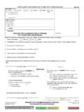
1 RF 400/410/2000. REPAIR form . HydroGuard 400/410/2000. Pressure Balancing Valves All Models DESCRIPTION. The Hydroguard 400/410 pressure balancing valve insures FIGURE 1: Determine Your Valve Model safety to the bather upon hot or cold Water supply pressure failure or change. The internal balance chamber forces the 5 U7. hot or cold Water supply pressure to be equalized should HOT MODEL. NUMBER. DATE. CODE COLD. either pressure fail or change. To ensure correct REPAIR parts are installed, determine valve model by referring to 40. bonnet label (see Figure 1). Once model number is deter- 1-0. PA 00. RT. NO 5 UOD7EL. mined, refer to appropriate chart to ensure correct kit has . M. been supplied. Since kits contain parts for multiple POWERS. models, discard extra parts. Balance Chamber Installation: REPAIR INSTRUCTIONS 1. Apply a small amount of silicone supplied to inner surface Replace Balance chamber if of valve body and inlet O -rings of balance chamber.
2 The discharge Water temperature is variable or untempered. 2. Align chamber and valve body inlet holes. The valve leaks after it is completely shut off. 3. Slowly push chamber in, being very careful not to pinch Balance Chamber Removal: side O -rings (item 5A in figures 5 and 6). TO REMOVE THE BALANCE CHAMBER, using a bal- Replace Gasket and Disks if . ance chamber extraction tool (Part No. 401-202) is highly Flow continues after mixer is turned off. recommended. To use the extraction tool, follow instruc- Stem or handle is damaged. tions below: Water leaks at stem and/or bonnet. a. Insert hooked ends of extraction tool into HOT and COLD outlet ports of the balance chamber (see Figure Gasket and Disc Replacement: 2). 1. Replace all gaskets and discs according to the dia- grams as shown in figures 5 and 6. Use silicone gel b. Insert screwdriver down through end of extraction tool. provided on all O -rings and related surfaces.
3 Never c. Place a wood or plastic block (do not use metal) use grease. between screwdriver and valve body. Firmly ease 2. The number of flat washers required for installation on screwdriver away and downward, using wood for stem varies with each model. Refer to Figure 3 when added leverage as cartridge is gradually pulled out. replacing the washers. Figure 2: Balance Chamber Removal Figure 3: Number of Flat Washers to Use By Model Washer(s) Models 1-3, 5, 7, 8 1 washer Models 4, 6 4 washers NOTE: Be certain to refer to Figure 5 or Figure 6 to locate the appropriate parts and kits for your model. RF 400/410/2000 Page 2. REPAIR INSTRUCTIONS (CONTINUED). Replace Stem and Plate if NOTE: For reversed inlets, be sure to clearly identify Flow continues after mixer is turned off. the Hot and Cold inlet ports to avoid confusion Water leaks at stem and/or bonnet. during future maintenance. Stem and Plate Replacement Figure 4: Standard Inlets Figure 4A: Reversed Inlets 1.
4 FOR STANDARD INLETS: Place the plate Outlet Outlet directly on top of the balance chamber (see Figure 4 for proper orientation of Notch in Handle +. plate). Must point to (top) Spline HOT inlet Must FACE Outlet 2. The flat notch on the splined stem must COLD HOT. COLD. FACE the outlet port of the valve body for HOT. Hot Cold COLD. HOT. Water Water standard inlets (cold Water entering COLD Water Water inlet port). Notch in Handle +. 3. FOR REVERSED INLETS: (cold Water Must Point (top) Spline to COLD Inlet Must Face AWAY. entering hot inlet port), the flat notch on the From Outlet splined stem must face AWAY FROM the Orientation of Plate and Stem Assembly Orientation of Plate and Stem Assembly for STANDARD Inlets for REVERSED inlets outlet port. See Figure 4A for proper orien- (Cold Water into COLD port) (Cold Water into Hot port). tation of plate. PARTS. Figure 5: HydroGuard 400/410.
5 Models 1-3, 5, 7, 8. REPAIR Kit Includes REPAIR Where (Numbers below correspond with Troubleshooting Kit No. Used numbers in Figure 5 above). 1. Cartridge slips while seated in body. Oversize 410 Inlet 410-570* 400/410 1 4, 5A, 5B*, 6**. 2. Flow continues after mixer is turned off and all Searl Kit* All Models other seals have been replaced. 1. Water leak at stem and/or bonnet. Gasket and Disc 410-182 400/410 1 4, 5A, 6**. 2. Flow continues after mixer is turned off. Replacement All Models 1. Variable or untempered discharge temperature. Balance Chamber 410-183 400: Models 1-3 3 5, 5A, 13, 15, 16**. 2. Leakage after mixed is turned off. (for any 410: Models 1-3, 7, 8. 3-port valve) Metal and Plastic Bonnet 1. Flow continues after mixer is turned off. Stem and Plate 410-378 400: Models 1-3 1 4, 7 9**. 2. Handle splines on stem damaged. Replacement 410: All Models 410-378A 419's only 1 4, 7 9**.
6 1-4, 7-9** (shorter stem). * When using oversize O-ring (item 5B), discard ONE of the two regular sized O-rings (5A) normally used and use item 5B in its place. ** Use O-ring only on Hydroguard 412/414. Others use gasket. ** Item 7 has brass stem and Celcon Plastic Mixing Plate (refer to Figures 4 and 4A). PLEASE NOTE: Some kits contain parts for more than one model. Discard additional parts as appropriate. RF 400/410/2000 Page 3. PARTS (CONTINUED). Figure 6: HydroGuard 400 - Models 4 & 6. HydroGuard 410 - Model 4. HydroGuard 2000 - Model 1. RF 400/410/2000 Page 4. MAXIMUM TEMPERATURE SETTING/HANDLE ROTATION STOP. MAXIMUM TEMPERATURE SETTING (refer to Figure 7). This must be set on the job and following any maintenance Figure 7: Maximum Temperature Setting or servicing to the valve. Mixer is factory set to pass full HOT Water . a. Loosen adjustment stop screw (do not remove). Gradually rotate stem counterclockwise to get desired maximum Water temperature.
7 (Maximum Temperature Stop will rotate long with the stem when the stem is rotated). b. Once stem has been rotated to desired temperature, slide adjustment stop clockwise until fin on adjustment stop touches the maximum temperature stop. c. While holding adjustment stop in place, tighten adjust- ment stop screw. d. Replace handle. Confirm maximum temperature has been set properly by operating the valve using the handle. Caution: Adjustment stop must be present for proper operation. 2006 Powers USA: Phone: Fax 229. 0526 Canada: Phone: Fax 1. 888. 882 .1979 RF 400/410/2000 0648 EDP# 6508770.