Transcription of REPORT DOCUMENTATION PAGE Form Approved
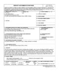
1 form Approved REPORT DOCUMENTATION PAGE OMB No. 0704-0188. The public reporting burden for this collection of information is estimated to average 1 hour per response, including the time for reviewing instructions, searching existing data sources, gathering and maintaining the data needed, and completing and reviewing the collection of information. Send comments regarding this burden estimate or any other aspect of this collection of information, including suggestions for reducing this burden, to Department of Defense, Washington Headquarters Services, Directorate for information on Operations and Reports (0704- 0188), 1215 Jefferson Davis Highway, Suite 1204, Arlington, VA 22202-4302. Respondents should be aware that notwithstanding any other provision of law, no person shall be subject to any penalty for failing to comply with a collection of information if it does not display a currently valid OMB control number. PLEASE DO NOT RETURN YOUR form TO THE ABOVE ADDRESS.
2 1. REPORT DATE (DD-MM-YYYY) 2. REPORT TYPE 3. DATES COVERED (From - To). 10-01-2013 Final 4. TITLE AND SUBTITLE 5a. CONTRACT NUMBER. Joint Ordnance Test Procedure (JOTP)-061. Hazards of Electromagnetic Radiation to Ordnance (HERO) Safety Test 5b. GRANT NUMBER. 5c. PROGRAM ELEMENT NUMBER. 6. AUTHORS 5d. PROJECT NUMBER. 5e. TASK NUMBER. 5f. WORK UNIT NUMBER. 7. PERFORMING ORGANIZATION NAME(S) AND ADDRESS(ES) 8. PERFORMING ORGANIZATION. Naval Ordnance Safety and Security Activity (NOSSA) REPORT NUMBER. Weapons Assessment (N8) JOTP-061. 3817 Strauss Avenue, Suite 108. Indian Head, MD 20640-5151. 9. SPONSORING/MONITORING AGENCY NAME(S) AND ADDRESS(ES) 10. SPONSOR/MONITOR'S. Range Infrastructure Division (CSTE-TM) ACRONYM(S). US Army Test and Evaluation Command 2202 Aberdeen Boulevard 11. SPONSOR/MONITOR'S REPORT . Aberdeen Proving Ground, MD 21005-5001 NUMBER(S). Same as item 8. 12. DISTRIBUTION/AVAILABILITY STATEMENT. Distribution Statement A.
3 Approved for public release; distribution is unlimited. 13. SUPPLEMENTARY NOTES. Defense Technical Information Center (DTIC), AD No.: 14. ABSTRACT. This document has been developed to address HERO safety testing. It is intended to act as the seminal HERO test procedures among a family of overarching safety procedures for tests simulating common environmental stimuli for the purpose of service assessment and testing of conventional (non-nuclear) munitions. 15. SUBJECT TERMS. joint service HERO safety munitions EME ordnance 16. SECURITY CLASSIFICATION OF: 17. LIMITATION OF 18. NUMBER 19a. NAME OF RESPONSIBLE PERSON. ABSTRACT OF. a. REPORT B. ABSTRACT C. THIS PAGE. pages . Unclassified Unclassified Unclassified 19b. TELEPHONE NUMBER (include area code). SAR 11. Standard form 298 (Rev. 8-98). Prescribed by ANSI Std. Z39-18. (This page is intentionally blank.). DEPARTMENT OF DEFENSE. JOINT ORDNANCE TEST. PROCEDURE (JOTP)-061. HAZARDS OF ELECTROMAGNETIC RADIATION TO.
4 ORDNANCE (HERO) SAFETY TEST. Joint Services Munition Safety Test Working Group Joint Ordnance Test Procedure (JOTP)-061. Hazards of Electromagnetic Radiation to Ordnance (HERO) Safety Test DOCUMENT DATE: TITLE AND SUBTITLE: 10 January 2013 Joint Ordnance Test Procedure (JOTP)-061. Hazards of Electromagnetic Radiation to Ordnance (HERO) Safety Test PREPARING ACTIVITY: SPONSORING ACTIVITY: Charles Denham Range Infrastructure Division (CSTE-TM). Naval Ordnance Safety and Security Activity (NOSSA) US Army Test and Evaluation Command Weapons Assessment (N8) 2202 Aberdeen Boulevard 3817 Strauss Avenue, Suite 108 Aberdeen Proving Ground, MD 21005-5001. Indian Head, MD 20640-5151. DISTRIBUTION STATEMENT: Distribution Statement A. Approved for public release; distribution is unlimited. ABSTRACT: This document has been developed to address HERO safety testing. It is intended to act as the seminal HERO test procedures among a family of overarching safety procedures for tests simulating common environmental stimuli for the purpose of service assessment and testing of conventional (non-nuclear).
5 Munitions. COORDINATION DRAFT REVIEWED BY: Naval Ordnance Safety and Security Activity (NOSSA). DOD Joint Weapon Safety Working Group (JWSWG). Joint Ordnance Commander's Group (JOCG) HERO Subcommittee PATH FORWARD: This Joint Ordnance Test Procedure (JOTP) shall serve as the US Joint Services Hazards of Electromagnetic Radiation to Ordnance (HERO) Safety Test Procedures with regards to conventional munitions until which time the content of this document is included in the next revision of Department of Defense Manual (DoDM) 3222 (Electromagnetic Compatibility and Electronic Warfare), and Standardization Agreement (STANAG 4370)/Allied environmental Conditions and Test Publication (AECTP) 500 (Electromagnetic environmental Effects Test and Verification) Category 508. (Ordnance/Munitions Verification Testing). Upon approval of the next revisions of DoDM 3222 and STANAG 4370/AECTP 500, thorough review of this document shall be conducted with the intent to supersede.
6 (This page is intentionally blank.). DEPARTMENT OF DEFENSE. JOINT ORDNANCE TEST PROCEDURE. *. Joint Ordnance Test Procedure (JOTP)-001 10 January 2013. DTIC AD No. HAZARDS OF ELECTROMAGNETIC RADIATION TO. ORDNANCE (HERO) SAFETY TEST. Page Paragraph 1. INTRODUCTION .. 2. 2. 2. 3. TEST CONDITIONS .. 2. 4. TESTS .. 5. 5. TEST ASSESSMENT AND ANALYSIS REPORT .. 5. Approved for public release; distribution unlimited. JOTP-061. 10 January 2013. 1. INTRODUCTION. This document has been developed to address HERO safety testing. It is intended to act as the seminal HERO test procedures among a family of overarching safety procedures for tests simulating common environmental stimuli for the purpose of service assessment and testing of conventional (non-nuclear) munitions. 2. SCOPE. a. Purpose. The purpose of this document is to guide personnel involved in the planning and execution of HERO testing and to support joint service approval of the weapon system.
7 B. Application. Data obtained through use of this document should be included in the munition safety data package. c. Limitations. This document is only applicable to conventional (non-nuclear) munitions. This document is not intended to be used to aid the assessment of effectiveness, reliability or performance of a munition. 3. TEST CONDITIONS. a. Test Item Configuration. Ordnance may be authorized for use with multiple platform/systems, launchers, interface cables, and diagnostic equipment. All versions of these systems and equipment must be considered for HERO as they can have significant impact on the susceptibility of the ordnance item. Furthermore, it is important to recognize that the ordnance item may be configured differently as it transitions through the various phases of its Stockpile-to-Safe Separation Sequence (S4). Each configuration may, therefore, exhibit significantly different responses to the Electromagnetic Environment (EME); that is, may be very susceptible in one configuration, but completely unresponsive at another.
8 Consequently, all authorized platform/systems, launchers, interface cables, and diagnostic equipment and S4 phases ( , transportation/storage, assembly/disassembly, handling/loading, staged, platform loaded, and immediate post-launch). shall be considered as part of the HERO test and/or analysis. Inasmuch as the handling and loading phase (man in the loop) is the most crucial part of the evaluation process, HERO testing shall be conducted during this phase as described in Military Handbook (MIL-HDBK)-240. Relevant ordnance phases involving unrestricted and restricted levels can be found in Military 2. JOTP-061. 10 January 2013. Standard (MIL-STD)-464C and MIL-HDBK-240 provides detailed explanations and test procedures. b. Instrumentation. (1) Electrically Initiated Device (EID) instrumentation shall be capable of detecting and monitoring Radio Frequency (RF)-induced responses of EIDs contained in an ordnance system. As such, the instrumentation sensitivity shall be sufficient to establish the required pass/fail margin (P/FM) when the system is exposed to its expected operational EME.
9 In addition, the instrumentation response time shall be at least as fast as the thermal time constant of the EID being monitored. (2) During the HERO test, every effort should be made to select and implement an instrumentation package that will not impact the RF characteristics of the ordnance. In addition, the instrumentation system should not be adversely affected by the EME. MIL-HDBK-240. provides discussions on the various types of instrumentation systems used in ordnance testing, characteristics of an instrumentation system, the selection rationale, and other types of instrumentation used for unique non-bridgewire EIDs or firing circuits. c. Calibration. The Electromagnetic (EM) energy coupling into an EID is dependent on the impedance matching of the EID bridgewire/circuit and the ordnance system firing circuit. Instrumentation systems shall use the actual EID. Calibrate the instrumentation system by applying a step input of direct current with a duration that is at least 10 times the thermal response time of the EID.
10 An ammeter with at least one-half percent accuracy may be used to measure this pulse. The output of the sensor/transducer is measured and recorded. This output versus input is the calibration for the system. The calibration establishes the relationship of the step input into the EID bridgewire to the output parameter of the instrumentation. This instrumentation output value can then be related to the EID's Maximum No-Fire Stimulus (MNFS) established by the manufacturer or Department of Defense (DoD) agency. The calibration will also establish the instrumentation system's minimum sensitivity and dynamic range. There are three important factors to calibrating the system: (1) All system components (receiver, recorder, computers, and so forth) that will be used during the test and all component settings must be calibrated. (2) The direct current pulse must be inputted directly into each individual bridgewire lead or an analysis of the EID circuit must be performed to determine the amount of current applied to the particular bridgewire being monitored.
