Transcription of Requirements for Soldered Electrical and Electronic ... - IPC
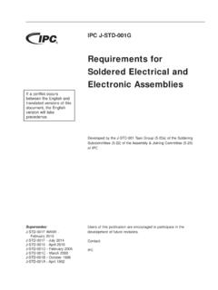
1 IPC J-STD-001H.. Requirements for Soldered Electrical and Electronic Assemblies If a conflict occurs between the English and translated versions of this document, the English version will take precedence. Developed by the J-STD-001 Task Group (5-22A), J-STD-001 Task Group Europe (5-22A-EU), J-STD-001 Task Group China (5-22 ACN). of the Assembly and Joining Committees (5-20) of IPC. Supersedes: Users of this publication are encouraged to participate in the J-STD-001G - October 2017 development of future revisions. J-STD-001F WAM1 - February 2016 Contact: J-STD-001F - July 2014. J-STD-001E - April 2010 IPC. J-STD-001D - February 2005.
2 J-STD-001C - March 2000. J-STD-001B - October 1996. J-STD-001A - April 1992. September 2020 IPC J-STD-001H. Table of Contents GENERAL .. 1 Inspection Methodology .. 6. Scope .. 1 Process Verification 6. 1 Visual 6. Classification .. 1 Facilities .. 7. Measurement Units and Applications .. 1 Environmental 7. Verification of Dimensions .. 2 Field Assembly 8. Definition of Requirements .. 2 Health and Safety .. 8. Hardware Defects and Process Indicators .. 2 Electrostatic Discharge (ESD).. 8. Material and Process Nonconformance .. 2. APPLICABLE DOCUMENTS .. 9. Procedures for Specialized 2 IPC .. 9. Process Control Requirements .. 3 JEDEC.
3 9. Opportunities Determination .. 3 Joint Industry Standards .. 10. Statistical Process 3 ASTM .. 10. Order of Precedence .. 4 EOS/ESD Association, Inc.. 10. 4 International Electrotechnical Commission .. 10. Terms and 4 SAE International .. 10. Circumferential Solder Separation Military Standards .. 10. (Area Void of Solder) .. 4. Aerospace Industries Association / National Diameter .. 4 Aeronautics Standards .. 10. Disposition .. 4. MATERIALS, COMPONENTS AND EQUIPMENT. Electrical Clearance .. 4 Requirements .. 11. Engineering Documentation .. 4 11. FOD (Foreign Object Debris) .. 4 Solder .. 11. High Voltage .. 4 Solder Pb-Free.
4 11. Manufacturer .. 5 Solder Purity Maintenance .. 11. Objective Evidence .. 5 Flux .. 12. Process Control .. 5 Flux Application .. 12. 5 Adhesives .. 12. Solder Destination Side .. 5 Chemical 12. Solder Source Side .. 5 13. Solder 5 Component and Seal Damage .. 13. Supplier .. 5 Coating Meniscus .. 13. Tempered Leads .. 5 Tools and Equipment .. 13. User .. 5. GENERAL SOLDERING AND ASSEMBLY. Wire 5 Requirements .. 15. Wire 5 Solderability .. 15. Requirements Flowdown .. 6 Solderability Maintenance .. 15. Personnel Proficiency .. 6 Removal of Component Surface Finishes .. 15. X-Ray Specific Personnel Proficiency .. 6 Gold Removal.
5 15. Acceptance 6 Other Metallic Surface Finishes Removal .. 15. ix IPC J-STD-001H September 2020. Thermal Protection .. 15 General Requirements .. 23. Rework of Nonsolderable Parts .. 16 Turret and Straight Pin Terminals .. 24. Preprocessing Cleanliness Requirements .. 16 Bifurcated Terminals .. 25. General Part Mounting 16 Slotted Terminals .. 26. General 16 Hook 27. Lead Deformation Limits .. 16 Pierced or Perforated Terminals .. 27. Hole 16 Cup and Hollow Cylindrical Terminals . Metal-Cased Component Isolation .. 16 Placement .. 27. Adhesive Coverage Limits .. 16 Series 28. Mounting of Parts on Parts (Stacking of Soldering to 28.)
6 Components) .. 16 Bifurcated 28. Connectors and Contact Areas .. 16 Slotted 28. Handling of 16 Cup and Hollow Cylindrical Terminals . Soldering .. 28. 17. Jumper Wires .. 29. Controlled Cooling .. 17. 29. 17. Wire 29. Holding Devices and Materials .. 17. Wire Staking .. 29. Machine 17. Unpopulated Land or Via Lap 29. Nonreflow Soldering .. 17. Supported Holes .. 29. Reflow Soldering .. 17. SMT .. 29. Solder 17. Exposed 18 THROUGH-HOLE MOUNTING AND. TERMINATIONS .. 31. Solder Connection Anomalies .. 18. Through-Hole Terminations General .. 31. Partially Visible or Hidden Solder 18 Lead 32. Heat Shrinkable Soldering Devices .. 18 Termination 32.
7 Threaded Fasteners .. 19 Lead Trimming .. 33. Torque .. 20 Interfacial Connections .. 33. Supported Holes .. 33. WIRES AND TERMINAL CONNECTIONS .. 21 Solder Application .. 33. Wire and Cable Preparation .. 21 Through-Hole Component Lead 33. Insulation Damage .. 21 Coating Meniscus in Solder .. 34. Strand 21 Unsupported Holes .. 34. Tinning of Stranded Wire Forming .. 21 Lead Termination Requirements for Solder Terminals .. 22 Unsupported Holes .. 34. Bifurcated, Turret and Slotted Terminal SURFACE MOUNTING OF COMPONENTS .. 35. Installation .. 22. Surface Mount Device Lead .. 35. Shank Damage .. 22 Plastic 35. Flange Damage .. 22 Forming.
8 35. Flared Flange 22 Unintentional 36. Terminal Mounting Mechanical .. 22 Flat Pack Parallelism .. 36. Terminal Mounting Electrical .. 22 Surface Mount Device Lead Bends .. 36. Terminal Mounting Soldering .. 23 Flattened Leads .. 36. Mounting to Terminals .. 23 Parts Not Configured for Surface Mounting .. 36. x September 2020 IPC J-STD-001H. Leaded Component Body 36 Level 2 Minor Changes with Supporting Axial-Leaded Components .. 36 Objective Evidence .. 64. Parts Configured for Butt/I Lead Mounting .. 36 Foreign Object Debris (FOD) .. 64. Installation of Surface Mount Components .. 36 Visible 65. Soldering 36 Non-ionic 65. Misaligned Components.
9 37 Ultrasonic Cleaning Processes .. 65. Unspecified and Special Requirements .. 37 Guidance 65. Bottom Only Chip Component Terminations .. 38 PRINTED BOARD Requirements .. 67. Rectangular or Square End Chip Printed Board Damage .. 67. Components 1, 2, 3 or 5 Side Termination(s) .. 39 Blistering/Delamination .. 67. Cylindrical End Cap Terminations .. 41 Weave Exposure/Cut Fibers .. 67. Castellated 43 67. Flat Gull Wing Leads .. 44 Edge Delamination .. 67. Round or Flattened (Coined) Gull Land/Conductor Separation .. 67. Wing Leads .. 45 Land/Conductor Reduction in Size .. 67. J Lead 46 Flexible Circuitry 67. Butt/I Terminations.
10 47 Flexible Circuitry Damage .. 67. Flat Lug 49 Burns .. 67. Tall Profile Components Having Bottom Non- Soldered Edge Contacts .. 67. Only Terminations .. 50. 67. Inward Formed L-Shaped Ribbon 51. Crazing .. 68. Surface Mount Area Array Packages .. 52. Bottom Termination Components (BTC).. 55 Marking .. 68. Components with Bottom Thermal Plane Bow and Twist (Warpage) .. 68. Terminations (D-Pak).. 56 68. Flattened Post Terminations .. 57. COATING, ENCAPSULATION AND STAKING. P-Style 58 (ADHESIVE).. 69. Vertical Cylindrical Cans with Outward Conformal Coating .. 69. L-Shaped Lead 59. 69. Wrapped Terminals .. 61. 69. Flexible and Rigid-Flex Printed Circuitry with Flat Unformed Leads.
