Transcription of RESERVE POWER - EnerSys - EMEA
1 OPERATION GUIDEFORHYBRID APPLICATIONSRESERVEPOWER1. ApplicationsPowerSafe SBS EON Technology solutions are well proven instand by and cyclic applications, recent developments have focusedon improving robustness in harsh environments and challengingoperating conditions, so that today EON Technology now has highercyclic performance, improved endurance at high temperature and theability to operate in partial state of charge, providing that theoperating conditions are well understood. Where mains grid POWER is not available the POWER requirement istypically alternately supplied by diesel generator or battery bank butcan also incorporate renewable energy sources such as wind turbineor PV array. In these off grid hybrid applications the battery can besubjected to warm ambient temperature with regular cyclic duty typically 1 cycle per grid hybrid applications can be split into two sub categories asshown in table 2 provides a summary of the operating parameters (charging)that will deliver optimum service life and performance relative to thetype of General Operating Operating Temperature RangeThe recommended operating temperature range for PowerSafe SBSEON Technology monoblocs and cells in hybrid applications is -40 Cto +50 C.
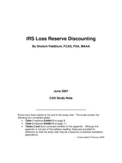
2 Optimum life and performance are attained at +20 C,however, with the correct controls in place, cyclic performance inhybrid applications is not impacted by elevated temperatures(providing that the maximum battery temperature is not allowed toexceed +50 C). StoragePowerSafe SBS EON Technology monoblocs and cells types have ashelf life of 2 years when stored at 20 C. Higher temperaturesincrease the rate of self discharge and reduce storage 1 gives the relationship between storage time, open circuitvoltage (OCV) and state of charge as a function of Freshening ChargePowerSafe SBS EON Technology monoblocs and cells types must begiven a freshing charge when the OCV approaches Volts/cell orwhen maximum storage time is reached (whichever occurs first).The freshening charge should be conducted using constant voltage inthe range of to volts per cell for a period of 24 hours.
3 Theminimum charge current should be equivalent to C10 Amps, themaximum value is maximum storage times between refresh charge andrecommended OCV audit frequency is given in the table CommissioningPrior to commencement of cyclic duty, the battery must be given acommissioning charge. This shall consist of 24 hours charge at avoltage equivalent to Volts/cell with no load Fast ChargingFast charge is recommended for frequent discharge cyclicapplications. In such applications the rectifier output voltage shouldbe set at Volts/cell (20 C). Charging Current LimitDue to the very low internal resistance PowerSafe SBS EONmonoblocs and cells will accept unlimited current during recharge,with minimum acceptable current equivalent to the load + DisposalPowerSafe SBS EON Technology monoblocs and cells are of life batteries must be packaged and transported according toprevailing transportation rules and regulations.
4 End of life batteriesmust be disposed of in compliance with local and national laws by alicensed battery Cyclic Operation Cyclic PerformanceEON Technology has been developed to retain the long float lifecharacteristics associated with standard PowerSafe SBS technologyand has the added capability to deliver high performance in harshapplications where cyclic duty optimal cyclic performance shown in figure 2 is based on thebattery being returned to full state of charge between dischargecycles. It is possible to operate SBS EON Technology monoblocs andcells in controlled partial state of charge condition, however, in suchsituations it is very important to ensure that the battery is periodicallyreturned to full state charge to maintain battery state of health. It isrecommended to contact your EnerSys representative to obtainadditional information and guidance for such psoc Circuit Voltage per CellApprox.
5 State of Charge (%)Months0 6 12 18 24 30 36 42 48+40 C+30 C+25 C+20 C+10 CFigure 1 Controlled full state of charge:An operating mode with regular cyclic duty where the battery isreturned to full state of charge between discharge cycles. The dutycycle is designed to optimised balanced battery life and operatingexpenditure savings. Can be subjected to high partial state of charge:An operating mode with regular cyclic duty where the battery isdeliberately operated in partial state of charge to maximiseoperating expenditure savings. The battery is periodically returnedto full state of charge when predefined trigger points are be subjected to high ambient SBS EON Technology Charge Parameter for Optimised Life and PerformanceHybrid operation Boost voltage equivalent to @ 20 Cto full state of Charge current - minimum ,chargemaximum unlimitedReturn to full state of charge betweendischarge cycles.
6 Optimum charge factor 103% of discharged AhHybrid operation Boost voltage equivalent to @ 20 C in partial state of to return to 95% state of current - minimum , (controlled PSOC) maximum unlimited- exampleFull recharge every 10 daysEnerSys will consider variations in controlled psoc operation as necessary - please contact your local representative to discuss details2 Table 1 Table 2 TemperatureStorage Time OCV Audit Interval( C / F)(Months)(Months)+10 / +50486+15 / +59346+20 / +68244+25 / +77174+30 / +86123+35 / + +40 / + DischargeIt is recommended to measure discharge by means of an Ah countingdevice with accuracy 1% of the expected current range. A lowvoltage disconnect should be used to protect the battery fromabusive over discharge (typically for 48V nominal systemvoltage).
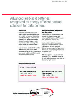
7 As a secondary control measure the discharge may be stopped andrecharge commenced when the on load battery voltage falls to thelevel equivalent to the configured depth of discharge in the dutycycle, using the curve for PowerSafe SBS EON as shown in figure an example a 48V system could be set up for 60% DoD in normaloperation, with an end of discharge voltage trigger of abnormal situations where a generator fails to start, a partialload disconnect at 47V (70% DoD) and low voltage disconnect (80% DoD) should be applied to protect the battery fromabusive over Recharge Controlled recharge can be achieved by Ah counting using a devicewith accuracy 1% of the expected current systems where control of charge factor is not possible, it may bepossible to estimate time to full state of charge by using thecalculation.
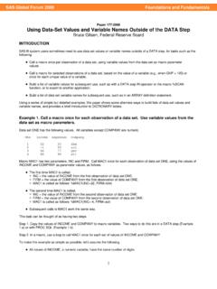
8 Recharge time (hrs) = 2* (( x discharged Ah) / current limit) +1 Indication of time to full state of charge using the above formula forvarious depths of discharge and current limits is shown in figure time to reach full state of charge is influenced by batterytemperature and charge voltage during the ) Where Ah counting is used to control the recharge ( ofdischarged Ah is returned) the battery voltage can be maintainedat a constant Volts/cell provided that the battery temperatureis controlled at or below +50 C discharged Ah returned. 2) Where time based recharge is used, temperature compensation forcharge voltage should be applied at the rates shown in figure a secondary control measure the recharge to full state of chargecan be determined as a function current absorbed by the battery andtime : if the current being absorbed reaches , full state ofcharge can be considered as attained after 1 additional hour ofcharge from this point.
9 For guidance on PSoC operation pleasecontact your EnerSys representative where a recommendation can begiven on a case-by-case rectifier voltage cannot be adjusted to values > Volts/cellto compensate for temperatures below 20 C, the time to full state ofcharge will be increased. For additional information and guidance onthis, please contact your EnerSys Data RecordingIt is recommended that as a minimum, the following information berecorded by means of regular data logging which the user mustmake available to EnerSys to validate any warranty ) The number of cycles performed and the depth of discharge( dod ) of each ) The duration of each discharge and charge cycle, and the Ah inand ) Full details of the recharge voltage/current profile for the last50 ) A full history of the ambient and battery surface temperatures,recorded at regular intervals throughout battery operation and )
10 The time and date of each event (an event is defined as thestart /stop of the battery discharge, the start/stop of the batteryrecharge, the start stop of any generator input POWER or other inputpower source, etc). Per CellTemperature ( C)Fast Charge Temperature CorrectionFigure 5 Time (hrs)Depth of Discharge 1816141210864200%10%20%30%40%50%60%70%80 %90%100%110% Amps Amps Amps Amps 1C10 Amps Time to Full State of ChargeAs a Function of Current Limit and Depth of Discharge(Recharge )Figure 40 500 1000 1500 2000 2500 3000 3500 4000 4500 5000 5500 6000 6500 7000 7500 8000 8500 9000 10 15 20 25 30 35 40 45 50 55 60 65 70 Fast charge cycles as a function of depth of discharge Number of Cycles% Depth of DischargeCycle Life in Fast Charge Applications(When Charged in Accordance with EnerSys Charging Strategy)