Transcription of Residential HVAC Worksheet
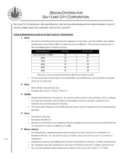
1 Building Services & Civil Enforcement 801-535- 6000, fax 801-535-7750451 South State Street, Room 215 PO Box 145490 Salt Lake City, Utah 84111 Salt Lake City, Utah 84114-5490 BLD #DateReceived byValuationOffice only U p d a te d 12 / 2012 Residential HVAC WorksheetManual J / S SummaryNOTE: The load calculation must be calculated on a room basis. Room loads are a mandatory requirement for making Manual D duct sizing calculations. This sheet has been developed for homs built in Utah s dry dimares- do not use for other climate InformationProjectLocationHtgAltitude ft fDesign ConditionsAssume no higher than 63 f unless there is ventilation air or significant duct leakage or heat gainClgOutside dbInside dbDesign TDEntering wb fIf design conditions used are not those listed in Table 1 / 1A Manual 3.
2 Please quality# of fireplacesSummaryManual J heat loss btuhTemp rise range to fManual J sensible gain btuhCalculated SHRH eating fan CFML atent gain btuhHtg design TD fTotal gain btuhCooling fan CFMUse SHR to determine cooling CFM / tonHeating EquipmentFurnace manufacturerSea level.
3 Input btuhModel #OutputAFUEA ltitude adjusted outputMultistageIf yes, provideAltitude adjusted lowest outputIf adjusted output is greater than times the total heating load , please justifyCooling EquipmentAC manufacturerTotal capacity btuhModel #Actual SEER rating w/ selection coil, furnace, & meteringSEERM eteringSensible capacity btuhLatent capacity btuhEvaporator coil manufacturerModel #TXVA ttach manufacturer s data showing actual cooling capacity and actual SEER using these componentsIf cooling capacity is greater than times the total heating load.
4 Please justifyMultistage f f f f fManual J / S Summary Instructions The load information asked for on the summary must be taken from the actual load calculation completed on the project name, lot number- information that matches the plan city or town must be reasonably close to actual location. Software used may not have the specific location in the Dry Bulb, Inside Dry BulbTemperature data should be from Table 1 or Table 1A of ACCA Manual J.
5 It is understood that there may be situations where a slight adjustment to this values is necessary. For example; there may be areas in the Salt Lake Valley where the low temperature is historically lower than the airport temperature. If values are adjusted- please justify the adjustment. Provide both heating (htg) and cooling (clg) design temperatures. If inside or outside design conditions listed are not the same values listed in Manual J, explain why the different values were WBThe entering wet-bulb represents the default value wet-bulb temperature across the evaporator coil.
6 This will typically be 63 f (75 f dry bulb) relative humidity). A higher wb temperature will result from duct leakage, un-insulated duct or ventilation air- any condition that raises the return air temperature. Use this wb temperature when selecting cooling condenser from manufacturer s comprehensive TDTD: the temperature difference between inside and outside design calculations are based on the Construction Quality. Version 7 of Manual ] uses Best, Average or Poor to evaluate Infiltration. Version 8AE uses Tight, Semi-Tight, Average, Semi-Loose and Loose to evaluate.
7 Version 8 goes into very specific detail for a more accurate number. Note method used on summary. Open firebox fireplaces that draw air from inside the home must be included, even if there is a 4 combustion air flex bring air into the fireplace. Sealed, direct vent type fireplaces should not be counted. Methods include: Simplified / Default Method- taken from Table 5A; Component Leakage Area Method- calculating infiltration based on individual leakage points taken from Table 5C of Manual J8; or Blower Door Method, where the actual leakage is based on a blower door test on the J Heat LossThis is the whole house winter heat loss taken directly from the completed attached Load Calculation.
8 Load must account for all factors such as loss building components as well as loss through infiltration, ventilation, and duct FanHeating airflow typically may be lower than cooling cfm. Adjusted to insure the temperature rise across the heat exchanger falls within the range specified by the manufacturer. Software will often do this calculation and provide a correct heating cfm. See Manual S Section 2-6 - Rise ( f) = Output Capacity ( x heating cfm)Manufacturer s Temperature Rise RangeRange taken from manufacturer s performance data.
9 Various manufacturers may certify ranges from 20 - 70 J Sensible GainThe whole house summer heat gain taken directly from the completed attached Load Calculation. Load must account for all factors including gain through building components, solar gain, infiltration, ventilation and ducts. Also includes the sensible internal gains from appliances and people. Manual 3 Latent GainThe gains due to moisture in the air. Large latent load are typically from moisture migration into the home from outside in humid climates.
10 People, cooking, plants, bathing and laundry washing can all add to the latent load in a home. Total GainThe combined total of the sensible and latent gain. May be referred to as Total Cooling Load. SHR- Sensible Heat RatioUse to determine Cooling cfm per ton. The ratio of sensible heat gain to total heat gain. SHR = Sensible Heat Gain Total Heat Gain. Recommended air flows: If SHR is below select 350 cfm / ton; if SHR is between & select 400 cfm; if SHR is greater than , select 450 cfm / ton. Note: This cfm is not the final cfm; additional adjustment may be required for Altitude.