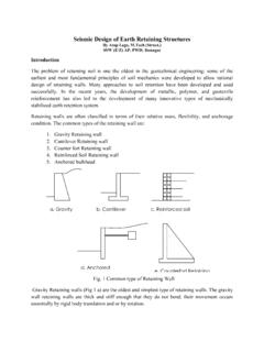
Transcription of RETAINING WALL 22 INSTALLATION …
1 RETAINING WALLINSTALLATION INSTRUCTIONS22 RETAINING WALL INSTALLATION INSTRUCTIONSThe following INSTALLATION instructionsapply to Anchor RETAINING wall productsthat feature a rear lip. Where there arevariations, the appropriate informationhas been noted. LEVELING PAD COMPACTIOND iagram 2 EXCAVATIOND iagram 1 CONSTRUCTION OF THE NEXT COURSED iagram 3 CORE FILLD iagram 4 STAKE OUT THE WALLHave a surveyor stake out the wall s placement. Verify the locations with the project for the leveling pad to the lines and grades shown on the approved plans and excavate enough soil behind the wall for the geosynthetic reinforcement material. The trench for the leveling pad should be at least 12 inches wider than the block you areinstalling and 6 inches deeper than the height of the Diagram PADAn aggregate leveling pad is made of compactible base material of 3 4-inch minus (with fines).
2 The pad must extend at least 6 inches in front of and behind the first course of block and beat least 6 inches deep after compaction. If the planned grade along the wall front will change elevation, the leveling pad may bestepped up in 6-inch increments to match the grade change. Start at the lowest level and work upward whenever possible. (See page 29 for more information.)Compact the aggregate and make sure it s level front to back and side to side. Mist lightlywith water before Diagram COURSEThis is the most important step in the INSTALLATION process. Bury the base course of laying block at the lowest elevation of the wall. Remove the rear lip of the block by hitting from the back so that it will lie flat on the leveling first block level, front to back and side to side; lay subsequent blocks in same manner.
3 Place the blocks side by side, flush against each other, and make sure the blocks are in full contact with the leveling the wall is on an incline, don t slope the blocks; step them up so they remain consistentlylevel. (See page 29 for more information.)Use stringline along back edge of block to check for proper multiple-piece products, use the largest unit, 18 inches wide, for the base course. CONSTRUCTION OF THE NEXT COURSED iamond and Diamond Pro Clean any debris off the top of the the second course of blocks on top of the base course. Maintain running bond. Pull each block forward as far as possible to ensure the correct setback. See Diagram with drainage aggregate directly behind the block, adding 6 inches at a time followed by proper compaction. Add soil fill behind the aggregate.
4 Compact before the next course is t drive heavy equipment near the wall. Self-propelled compaction equipment should not be used within 4 feet of the ll need partial units to stay on bond. A circular saw with a masonry blade is recommendedfor cutting partial units. Use safety glasses and other protective equipment when you are using a block with cores that should be filled, fill prior to laying the next Diagram Stone and Diamond Pro Stone Cut Follow instructions as noted can install these products using any combination of the wall bond by placing units in a staggered relationship to the course pages 16 and 17 for INSTALLATION patterns for Highland Stone. See page 20 for Diamond Pro Stone Cut INSTALLATION best results, use a filter fabric, which should be placed directly behind the wall extendingfrom the bottom of the base course to the middle of the top course.
5 This will minimize material coming through the rough-hewn face texture of these products. We recommend anon-woven, 4- to 6-ounce fabric. See Diagram page 24 for more information about cap more information visit WALL INSTALLATION INSTRUCTIONSFor more information visit WALL INSTALLATION INSTRUCTIONS23 FILTER FABRICD iagram 5 DRAIN TILED iagram 6 DRAINAGE AGGREGATE Diagram 7 COMPACTION Diagram 8 DRAINAGE DESIGNEach project is unique. The grades on your site will determine at what level to install thedrain the drain tile as low as possible behind the wall so water drains down and away fromthe wall into a storm drain or to an area lower than the wall. See Diagram in the area behind the blocks with drainage aggregate, at least 12 inches from the may need to place and backfill several courses to achieve the proper drainage the drain tile with a geotextile sock which acts as a filter.
6 The drain tile outlet pipesshould be spaced not more than every 50 feet and at low points of the wall. In order forthe drainage aggregate to function properly, it must keep clear of regular soil fill. (See page 28 for more information.)COMPACTIONS hovel the backfill soil behind the drainage aggregate and compact with a hand-operated sure the aggregate is level with or slightly below the top of the base soil in front of the base course and compact. Base course should be to fill and compact. See Diagram (IF REQUIRED)Geosynthetic reinforcement is recommended for walls taller than 4 feet or walls situated in poor soils, supporting a driveway, etc. Consult a qualified engineer for design assistance. Check the wall construction plan for which courses will need any debris off the top layer of and cut the reinforcement to the design length in the cut grid when block heights are varied in a row, see page reinforcement has a design strength direction, which must be laid perpendicular to the the front edge of the material on the top course, 2 inches from the face of the the next course of blocks to secure it in keep it from wrinkling, pull the reinforcement taut and pin the back edge in place with stakes or drainage aggregate behind the blocks, then add the soil and compact it.
7 See Diagrams 7 and place the front edge of the reinforcement on top of the block, making sureit s within 2 inches of the face of the block. Correct placement ensures that you maximizethe connection strength and keep the batter minimum of 6 inches of backfill is required prior to operating vehicles on the reinforcement. Avoid sudden turning or Diagram GRADE AND SURFACE DRAINAGEP rotect the wall with a finished grade at the top and ensure proper water drainage away from the wall, use 6 inches of soil with low permeability. This will minimize water seeping into the soil and drainage aggregate behind the CLEANING AND RESTORATIONB rush off the wall and pick up any debris left from the construction the job superintendent in writing of the project s completion and that it is ready for final inspection and vegetation in front and on top of the wall will help reduce the chance of these Best Practices for construction will ensure the successful INSTALLATION ofAnchor Wall Systems products.
8 Jumper INSTALLATION Note: See page 38 for further NOTE: Always use appropriate equipment, including safety glasses or goggles andrespirators, when splitting, cutting or hammering WALLCONSTRUCTION DETAILS24 RETAINING WALL CONSTRUCTION DETAILSCAPPING A WALL STRAIGHT WALLP roper INSTALLATION of any Anchor RETAINING wall requiresthat running bond be maintained. Running bond occurswhen the blocks are centered over the vertical joints of theprevious course. This adds to wall stability and makes yourwall system aesthetically beautiful. CURVED WALLAny wall that is not perfectly straight will eventually runoff bond when using Diamond and Diamond Pro. Whenthis happens, skip a block position and place the next blockinto the next place where it is back on bond. Measure theremaining gap and cut a block to fit.
9 Once the partial unit is in place, glue with a concreteadhesive. Partial units should not be less than 5 inches and should not be placed directly on top of each other. Ifthe gap is larger than the length of one block, divide themeasurement by two and put two partial units in WALLCaps are trapezoidal and must be laid alternatively shortand long cap faces for a straight line. Always start cappingfrom the lowest CURVESLay out the cap units side by side and cut at least everyother cap to produce a uniform look. Start with the longside of the cap facing out and adjust to the CURVESLay cap units side by side with the short side facing out. In most circumstances, making two cuts on one cap andthen not cutting the cap on either side produces the most pleasing a 90 corner wall, the corner caps need to be saw-cutto achieve a 45 mitered UP CAPSIf a wall elevation changes, caps can be stacked where thewall steps up.
10 Begin laying caps at the lowest elevationchange and work your way back toward the previous stepup. Split a cap unit to create a rough face on the exposedside. Place the half unit directly on top of the cappedportion of the wall with all three split faces layout is complete and caps are saw-cut or split tosize, carefully glue with a concrete BONDFor more information visit cuts on every other blockGlue each capShort edgesFor more information visit more information visit to fit; glue in placeCut to fit;glue in placeSplit step unitCut to fit;glue in placeELEVATIONThe step can be construction drawings feature step or pavers can be used for treads. Check localbuilding codes for any tread depth COURSET horoughly compact the leveling pad. Lay out thebase course according to the wall design.